🔌Intro to Electrical Engineering Unit 8 Review
8.4 Resonance in RLC circuits
8.4 Resonance in RLC circuits
Unit & Topic Study Guides
Intro to Electrical Engineering
Electrical Quantities and Units
Ohm's Law: Understanding Resistance
Kirchhoff's Laws in Electrical Engineering
Circuit Analysis Techniques
Capacitance and Inductance
Transient Response: First-Order Circuits
Steady-State Sinusoidal Analysis
Semiconductor Basics in Electrical Engineering
Diodes and Circuits
BJTs: Bipolar Junction Transistors
Field-Effect Transistors in Electronics
Digital Systems Fundamentals
Boolean Algebra & Logic Gates
Combinational Logic Circuits
Sequential Logic Circuits
Signal Processing Fundamentals
Continuous-Time Signals & Systems
Fourier Series and Transforms
Sampling and Discrete-Time Signals
Z-Transforms in Discrete-Time Systems
Circuit Simulation Tools Overview
System Modeling & Analysis Tools
Case Studies in Electrical Engineering
Resonance Types
RLC circuits exhibit resonance when energy continuously swaps back and forth between the inductor's magnetic field and the capacitor's electric field. At one specific frequency, these energy exchanges balance perfectly, producing dramatic effects on impedance, current, and voltage. Resonance is the principle behind radio tuners, bandpass filters, and oscillator circuits.
Series Resonance
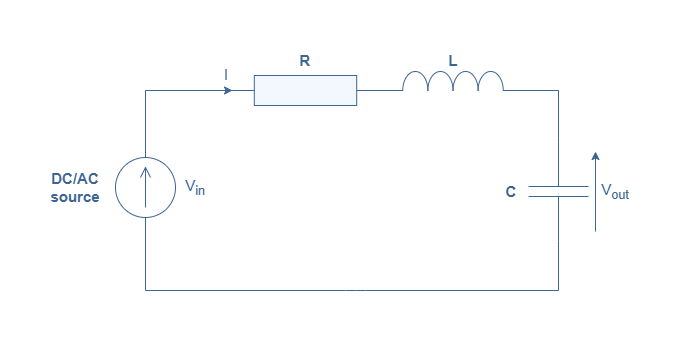
In a series RLC circuit, resonance occurs when the inductive reactance and the capacitive reactance become equal in magnitude. Since they carry opposite signs, they cancel each other out, leaving only the resistance to oppose current flow.
What happens at series resonance:
- Impedance drops to its minimum value, which is just . The reactive components effectively disappear.
- Current reaches its maximum because impedance is at its lowest. Think of it as the circuit offering the least resistance to current at this one frequency.
- The voltage across the inductor and the voltage across the capacitor are equal in magnitude but 180° out of phase, so they cancel when you sum them around the loop.
- The individual voltages across L and C can actually be much larger than the source voltage. This voltage magnification is directly related to the quality factor Q.
Applications: radio/TV tuners (selecting a station's frequency), bandpass filters, and series-fed oscillators.
Parallel Resonance
In a parallel RLC circuit, resonance occurs when the susceptances (imaginary parts of admittance) of the inductor and capacitor cancel. The behavior here is essentially the mirror image of series resonance.
What happens at parallel resonance:
- Impedance reaches its maximum value and is purely resistive. This is the opposite of the series case.
- Line current from the source is at its minimum because the high impedance restricts it.
- Large circulating currents flow between the inductor and capacitor internally, even though the current drawn from the source is small.
- The voltage across the parallel combination is maximum at resonance.
Applications: tank circuits in oscillators, parallel-tuned amplifier loads, and bandstop (notch) filters.
Resonant Frequency
The resonant frequency is the specific frequency where . It's denoted (in Hz) or (in rad/s).
To derive it, set the two reactances equal:
Solving for :
Converting to Hz:
This formula applies to both series and parallel RLC circuits (assuming ideal components). Notice that depends only on L and C, not on R. Resistance affects the shape of the resonance peak but not where it occurs.
Quick example: If and :
Resonance Characteristics

Quality Factor (Q)
The quality factor Q measures how "sharp" or selective the resonance peak is. A high-Q circuit responds strongly at the resonant frequency and very little at nearby frequencies. A low-Q circuit has a broader, flatter response.
One general definition relates Q to bandwidth:
But Q can also be calculated directly from component values, and the formulas differ between series and parallel circuits:
- Series RLC:
- Parallel RLC:
Notice the pattern: in a series circuit, smaller R gives higher Q (less energy lost per cycle). In a parallel circuit, larger R gives higher Q. This makes sense because in the series case R is in the current path and dissipates energy, while in the parallel case a larger parallel resistance means less current is shunted away from the LC tank.
Typical Q values in practice range from about 10 for simple circuits up to several hundred for precision tuned circuits.
Bandwidth
Bandwidth (also written as or ) is the range of frequencies over which the circuit's response stays within 3 dB of its peak value. The 3 dB points are also called half-power points because the power delivered at those frequencies is half the power at resonance.
The two half-power frequencies sit symmetrically (on a logarithmic scale) around . If you call them (lower) and (upper):
- At and , the current (series) or voltage (parallel) is times its peak value.
A narrow bandwidth means the circuit is highly selective, responding to a tight range of frequencies. A wide bandwidth means the circuit accepts a broader range.
Impedance at Resonance
The impedance behavior at resonance is what makes series and parallel circuits useful for different applications:
| Series RLC | Parallel RLC | |
|---|---|---|
| Impedance at resonance | Minimum: | Maximum: |
| Character | Purely resistive | Purely resistive |
| Result | Maximum current from source | Minimum current from source |
For the parallel case, can also be written as (using the parallel Q definition), which shows that higher Q means higher impedance at resonance.
Frequency Response
The frequency response curve plots how current (series) or voltage (parallel) varies as you sweep frequency across and around .
- Below resonance in a series RLC circuit, , so the circuit behaves capacitively (current leads voltage).
- Above resonance, , so the circuit behaves inductively (current lags voltage).
- At resonance, the phase angle between voltage and current is zero because the impedance is purely resistive.
The quality factor Q directly controls the shape of this curve. A high-Q circuit produces a tall, narrow peak. A low-Q circuit produces a short, wide peak. When you're asked to sketch a frequency response, mark at the peak, then mark and at the 3 dB points on either side. The distance between and is your bandwidth.