🔌Intro to Electrical Engineering Unit 22 Review
22.2 Schematic capture and netlist generation
22.2 Schematic capture and netlist generation
Unit & Topic Study Guides
Intro to Electrical Engineering
Electrical Quantities and Units
Ohm's Law: Understanding Resistance
Kirchhoff's Laws in Electrical Engineering
Circuit Analysis Techniques
Capacitance and Inductance
Transient Response: First-Order Circuits
Steady-State Sinusoidal Analysis
Semiconductor Basics in Electrical Engineering
Diodes and Circuits
BJTs: Bipolar Junction Transistors
Field-Effect Transistors in Electronics
Digital Systems Fundamentals
Boolean Algebra & Logic Gates
Combinational Logic Circuits
Sequential Logic Circuits
Signal Processing Fundamentals
Continuous-Time Signals & Systems
Fourier Series and Transforms
Sampling and Discrete-Time Signals
Z-Transforms in Discrete-Time Systems
Circuit Simulation Tools Overview
System Modeling & Analysis Tools
Case Studies in Electrical Engineering
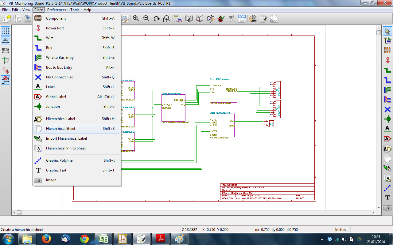
Schematic Capture
Schematic capture is how you turn a circuit idea into a digital diagram that software can actually work with. You place components, wire them together, and the tool generates a netlist, a text file describing every connection in your circuit. That netlist is what feeds into simulation (like SPICE) and PCB layout tools, so getting the schematic right is the foundation for everything that follows.
Creating and Editing Schematics
A schematic editor gives you a graphical canvas where you build your circuit visually. You select components, place them, draw wires between their pins, and add labels or notes to keep things organized.
- Most editors support hierarchical design, which means you can break a complex circuit into smaller sub-circuits (blocks) and then connect those blocks together at a higher level. This is similar to writing functions in code rather than putting everything in one giant file.
- For large designs, you'll often work across multiple sheets. The editor tracks connections between sheets so you don't lose connectivity.
Component Libraries and Placement
Every component you place comes from a symbol library, a collection of pre-drawn graphical symbols for resistors, capacitors, op-amps, transistors, and so on. Each symbol has defined pins that correspond to the real component's terminals.
- Libraries can be customized. If you're using a specific part that isn't in the default library, you can create a custom symbol for it.
- Good placement habits matter for readability: signal flow typically runs left to right, with power rails (VCC, VDD) at the top and ground at the bottom. Following these conventions makes your schematic much easier for others (and future you) to read.
Wiring and Connectivity
Wires represent the electrical connections between component pins. The editor usually provides auto-routing assistance so wires snap to pins cleanly.
- You can assign net names (labels) to wires. For example, labeling a wire "CLK" tells you and the software that every wire with that label is electrically connected, even if they aren't visually drawn together on the sheet.
- The editor maintains connectivity as you move components around, so rearranging your layout won't accidentally break connections.
Netlist and Design Validation
Netlist Generation
A netlist is a text file that lists every component in your schematic, its value or part number, and exactly which pins connect to which nets. Here's a simplified example of what a SPICE netlist might look like:
</>CodeR1 node1 node2 1k C1 node2 0 10u V1 node1 0 DC 5
Each line identifies a component, the nodes (nets) its pins connect to, and its value. The schematic editor generates this automatically from your drawing.
- Netlists serve as the input for circuit simulation (SPICE, etc.) and PCB layout tools.
- If your schematic has errors, the netlist will carry those errors forward, which is why validation matters before you generate it.
Design Rule Checking (DRC)
DRC is an automated check that scans your schematic for common mistakes before you move on to simulation or layout. Think of it as a spell-checker for your circuit.
Common issues DRC catches:
- Unconnected pins that should be wired to something
- Short circuits where two outputs drive the same net
- Missing component values (a resistor placed but never assigned a resistance)
- Duplicate reference designators (two components both labeled R1)
DRC rules can be customized. For instance, you might configure the tool to flag any input pin left floating as an error rather than just a warning.

Annotation and Back-Annotation
Annotation is the process of assigning unique reference designators to each component: R1, R2, C1, C2, U1, and so on. Most editors do this automatically, but you can also assign them manually.
Back-annotation works in the opposite direction. After you've done PCB layout, information flows back to the schematic, updating it with details like specific component footprints or pin swaps made during routing. This keeps the schematic and the physical board layout synchronized, which is critical if you need to revise the design later.
Documentation
Bill of Materials (BOM) Generation
A BOM is a complete list of every component in your design. The schematic editor generates it directly from the components you've placed.
A typical BOM includes:
- Reference designator (R1, C3, U2, etc.)
- Part number or manufacturer ID
- Component value or description
- Quantity needed
The BOM is used for ordering parts, guiding assembly, and verifying that nothing was missed before manufacturing.
Schematic Printouts and PDF Export
Schematic editors let you export your design as a PDF or print it directly. These exports are how you share designs for review, archive completed projects, or hand off documentation to a manufacturing team.
- Exported schematics typically include a title block with the project name, revision number, date, and designer name.
- Revision history tracking helps teams keep track of what changed between versions of a design.