🔌Intro to Electrical Engineering Unit 13 Review
13.2 Number systems and binary arithmetic
13.2 Number systems and binary arithmetic
Unit & Topic Study Guides
Intro to Electrical Engineering
Electrical Quantities and Units
Ohm's Law: Understanding Resistance
Kirchhoff's Laws in Electrical Engineering
Circuit Analysis Techniques
Capacitance and Inductance
Transient Response: First-Order Circuits
Steady-State Sinusoidal Analysis
Semiconductor Basics in Electrical Engineering
Diodes and Circuits
BJTs: Bipolar Junction Transistors
Field-Effect Transistors in Electronics
Digital Systems Fundamentals
Boolean Algebra & Logic Gates
Combinational Logic Circuits
Sequential Logic Circuits
Signal Processing Fundamentals
Continuous-Time Signals & Systems
Fourier Series and Transforms
Sampling and Discrete-Time Signals
Z-Transforms in Discrete-Time Systems
Circuit Simulation Tools Overview
System Modeling & Analysis Tools
Case Studies in Electrical Engineering
Number systems and binary arithmetic are the foundation of how digital systems represent and process information. Every operation a computer performs ultimately comes down to manipulating numbers in binary. This topic covers the four major number systems, how to convert between them, binary math, and the logic operations that drive digital circuits.
Number Systems
Binary, Decimal, Hexadecimal, and Octal
Each number system uses a different base, which determines how many unique digits it has and how place values work.
- Decimal (base 10) uses digits 0–9. This is the system you already know. Each place value is a power of 10 (ones, tens, hundreds, etc.).
- Binary (base 2) uses only 0 and 1. Each place value is a power of 2. This is the native language of digital hardware because circuits have two states: on and off.
- Hexadecimal (base 16) uses digits 0–9 and letters A–F (where A = 10, B = 11, ... F = 15). Each hex digit maps to exactly four binary bits, which makes it a convenient shorthand for long binary strings.
- Octal (base 8) uses digits 0–7. Each octal digit maps to exactly three binary bits. It's less common today but still shows up in some contexts like Unix file permissions.
Why so many systems? Binary is what hardware uses, but reading long strings of 1s and 0s is painful. Hex and octal let engineers write compact representations that convert to and from binary almost instantly.
Base Conversion
Decimal to Binary (repeated division by 2):
- Divide the decimal number by 2.
- Record the remainder (0 or 1).
- Take the quotient and divide by 2 again.
- Repeat until the quotient is 0.
- Read the remainders from bottom to top. That's your binary number.
Example: Convert 13 to binary.
- 13 ÷ 2 = 6 remainder 1
- 6 ÷ 2 = 3 remainder 0
- 3 ÷ 2 = 1 remainder 1
- 1 ÷ 2 = 0 remainder 1
Reading bottom to top:
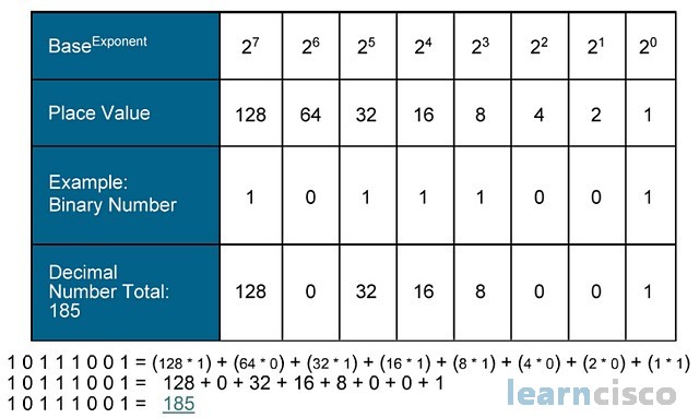
Binary to Decimal (sum of weighted bits):
Multiply each bit by its corresponding power of 2, then add the results.
Example:
Binary ↔ Hexadecimal:
Group the binary digits into sets of four (starting from the right), then replace each group with its hex equivalent.
Example: → group as → →
To go the other direction, expand each hex digit into four bits.
Binary ↔ Octal:
Same idea, but group into sets of three bits.
Example: → group as → →

Binary Arithmetic
Binary Addition and Subtraction
Binary addition follows the same column-by-column approach as decimal addition, but with only two digits:
- (write 0, carry 1)
- (write 1, carry 1)
Example: Add
</>Code1 0 1 1 + 0 1 1 0 --------- 1 0 0 0 1
Work right to left: , (write 0 carry 1), (write 0 carry 1), (write 0 carry 1), carry drops down as 1. Result: .
Binary subtraction is typically handled using two's complement (see next section), which lets you subtract by adding. This is a big deal in hardware design because it means the same adder circuit handles both addition and subtraction.
Signed vs. Unsigned Numbers and Two's Complement
Unsigned binary numbers represent only non-negative values. An -bit unsigned number can represent values from to . For example, 8 bits gives you 0–255.
Signed binary numbers need a way to represent negatives. The standard method is two's complement:
- The most significant bit (MSB) acts as the sign bit: 0 means positive, 1 means negative.
- Positive numbers look the same as unsigned.
- An -bit two's complement number ranges from to . For 8 bits, that's to .
Finding the two's complement (i.e., negating a number):
- Write the binary representation of the positive value.
- Flip every bit (0 → 1, 1 → 0). This is called the one's complement.
- Add 1 to the result.
Example: Find the 4-bit two's complement of 5.
- Flip bits:
- Add 1:
So in 4-bit two's complement is .
Subtraction via two's complement: To compute , find the two's complement of and add it to . Any carry out beyond the bit width is discarded.
Example: (which is in 4-bit unsigned, or you can treat it as signed).
- Two's complement of is .
- . Discard the carry → . Correct.
Bitwise Operations and Boolean Algebra
Bitwise Operations
Bitwise operations work on each pair of corresponding bits independently. They're used constantly in programming and hardware design for tasks like masking, toggling flags, and building logic circuits.
- AND: Output is 1 only if both input bits are 1.
- OR: Output is 1 if at least one input bit is 1.
- XOR (exclusive OR): Output is 1 if the inputs are different.
- NOT: Flips every bit (unary operation, applies to a single value).
Example with 4-bit numbers:
</>CodeA = 1 1 0 1 B = 1 0 1 1 -------------- AND = 1 0 0 1 OR = 1 1 1 1 XOR = 0 1 1 0 NOT A= 0 0 1 0
A practical use: if you want to check whether bit 2 of a byte is set, you AND the byte with . If the result is nonzero, that bit is 1. This is called bit masking.
Boolean Algebra
Boolean algebra is the math behind digital logic. It deals with variables that are either true (1) or false (0), combined using AND, OR, and NOT operations.
Boolean expressions describe the behavior of logic circuits. For example, the expression means "F is true when both A and B are true, or when C is false."
Several key laws let you simplify Boolean expressions (and therefore simplify circuits):
- Commutative: and
- Associative:
- Distributive:
- Identity: and
- Complement: and
- De Morgan's Theorems: and
De Morgan's theorems are especially worth memorizing. They show up constantly in simplifying logic expressions and in converting between AND/OR gate implementations.
Boolean algebra connects directly to circuit design: every Boolean expression can be built from AND, OR, and NOT gates. Simplifying the expression means fewer gates, which means cheaper, faster hardware.