🔌Intro to Electrical Engineering Unit 14 Review
14.3 Basic logic gates and universal gates
14.3 Basic logic gates and universal gates
Unit & Topic Study Guides
Intro to Electrical Engineering
Electrical Quantities and Units
Ohm's Law: Understanding Resistance
Kirchhoff's Laws in Electrical Engineering
Circuit Analysis Techniques
Capacitance and Inductance
Transient Response: First-Order Circuits
Steady-State Sinusoidal Analysis
Semiconductor Basics in Electrical Engineering
Diodes and Circuits
BJTs: Bipolar Junction Transistors
Field-Effect Transistors in Electronics
Digital Systems Fundamentals
Boolean Algebra & Logic Gates
Combinational Logic Circuits
Sequential Logic Circuits
Signal Processing Fundamentals
Continuous-Time Signals & Systems
Fourier Series and Transforms
Sampling and Discrete-Time Signals
Z-Transforms in Discrete-Time Systems
Circuit Simulation Tools Overview
System Modeling & Analysis Tools
Case Studies in Electrical Engineering
Logic gates are the building blocks of digital circuits. They take binary inputs (0s and 1s) and produce a binary output based on a specific logical rule. Understanding how each gate behaves is essential before you can analyze or design any digital system.
This section covers the three fundamental gates (AND, OR, NOT), two useful combination gates (XOR, XNOR), and the two universal gates (NAND, NOR) that can each replicate any other gate on their own.
Basic Logic Gates
AND and OR Gates
The AND gate outputs a 1 only when all of its inputs are 1. If any input is 0, the output is 0. Think of it like two switches wired in series: both switches must be closed for current to flow.
- Boolean expression:
| A | B | Y |
|---|---|---|
| 0 | 0 | 0 |
| 0 | 1 | 0 |
| 1 | 0 | 0 |
| 1 | 1 | 1 |
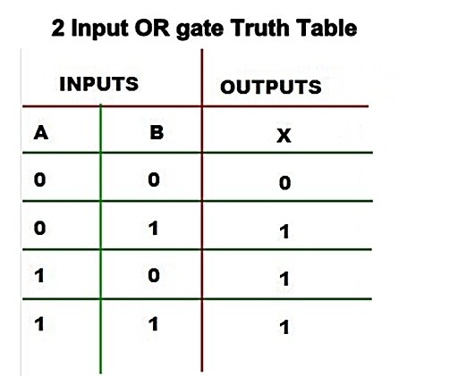
The OR gate outputs a 1 when at least one input is 1. The output is 0 only when every input is 0. This is like two switches wired in parallel: closing either one lets current through.
- Boolean expression:
| A | B | Y |
|---|---|---|
| 0 | 0 | 0 |
| 0 | 1 | 1 |
| 1 | 0 | 1 |
| 1 | 1 | 1 |
A common point of confusion: in Boolean algebra, means OR, not addition. And means AND, not multiplication. The symbols look like arithmetic, but the logic is different (though the truth tables happen to match for single-bit values in most cases).
NOT, XOR, and XNOR Gates
The NOT gate (also called an inverter) is the simplest gate. It has one input and flips it: 0 becomes 1, and 1 becomes 0.
- Boolean expression:
The XOR gate (exclusive OR) outputs a 1 when exactly one input is 1. If both inputs match (both 0 or both 1), the output is 0. XOR is especially useful in arithmetic circuits and error detection because it essentially checks whether two bits are different.
- Boolean expression:
| A | B | Y |
|---|---|---|
| 0 | 0 | 0 |
| 0 | 1 | 1 |
| 1 | 0 | 1 |
| 1 | 1 | 0 |
The XNOR gate (exclusive NOR) is the complement of XOR. It outputs a 1 when both inputs are the same. You can think of it as an equality checker.
- Boolean expression:
| A | B | Y |
|---|---|---|
| 0 | 0 | 1 |
| 0 | 1 | 0 |
| 1 | 0 | 0 |
| 1 | 1 | 1 |
Universal Gates
NAND and NOR Gates
A gate is called universal if you can build every other logic gate using only copies of that one gate. NAND and NOR are both universal. This matters in real-world chip design because manufacturing a circuit with just one type of gate is simpler and cheaper.
The NAND gate (NOT-AND) is an AND gate followed by a NOT. It outputs 0 only when all inputs are 1; otherwise it outputs 1.
- Boolean expression:
| A | B | Y |
|---|---|---|
| 0 | 0 | 1 |
| 0 | 1 | 1 |
| 1 | 0 | 1 |
| 1 | 1 | 0 |
Here's how you build the basic gates from NAND alone:
- NOT from NAND: Connect both inputs of a NAND gate to the same signal . Since , you get an inverter.
- AND from NAND: Take the output of a NAND gate and feed it into the NOT-from-NAND above. That inverts the NAND output back to AND.
- OR from NAND: First invert each input using step 1, then feed those inverted signals into a NAND gate. By De Morgan's theorem, .
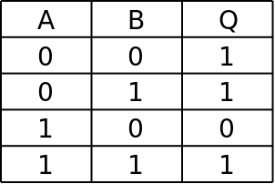
The NOR gate (NOT-OR) is an OR gate followed by a NOT. It outputs 1 only when all inputs are 0; otherwise it outputs 0.
- Boolean expression:
| A | B | Y |
|---|---|---|
| 0 | 0 | 1 |
| 0 | 1 | 0 |
| 1 | 0 | 0 |
| 1 | 1 | 0 |
NOR works the same way as NAND for universality, just with a mirrored approach. Tying both NOR inputs together gives you a NOT gate, and from there you can construct AND and OR.
Logic Circuits
Combinational and Sequential Logic
A logic circuit is a collection of interconnected gates that performs a specific function. These circuits fall into two categories.
Combinational logic circuits produce outputs that depend only on the current inputs. There's no memory involved. Given the same inputs, you'll always get the same output.
- Adders (add binary numbers)
- Multiplexers (select one of several inputs to pass through)
- Decoders (convert coded inputs into specific output lines)
Sequential logic circuits have outputs that depend on both the current inputs and the circuit's previous state. In other words, they have memory. A clock signal synchronizes when the circuit reads new inputs and updates its state.
- Flip-flops (store a single bit)
- Counters (count clock pulses)
- Shift registers (shift stored bits left or right)
Most real digital systems, from calculators to microcontrollers, combine both types. Combinational logic handles the data processing, and sequential logic handles storage and timing.