🔌Intro to Electrical Engineering Unit 20 Review
20.3 Quantization and analog-to-digital conversion
20.3 Quantization and analog-to-digital conversion
Unit & Topic Study Guides
Intro to Electrical Engineering
Electrical Quantities and Units
Ohm's Law: Understanding Resistance
Kirchhoff's Laws in Electrical Engineering
Circuit Analysis Techniques
Capacitance and Inductance
Transient Response: First-Order Circuits
Steady-State Sinusoidal Analysis
Semiconductor Basics in Electrical Engineering
Diodes and Circuits
BJTs: Bipolar Junction Transistors
Field-Effect Transistors in Electronics
Digital Systems Fundamentals
Boolean Algebra & Logic Gates
Combinational Logic Circuits
Sequential Logic Circuits
Signal Processing Fundamentals
Continuous-Time Signals & Systems
Fourier Series and Transforms
Sampling and Discrete-Time Signals
Z-Transforms in Discrete-Time Systems
Circuit Simulation Tools Overview
System Modeling & Analysis Tools
Case Studies in Electrical Engineering
Quantization Fundamentals
Quantization is the process of converting a continuous-valued signal into a discrete-valued signal. While sampling (covered earlier) discretizes the time axis, quantization discretizes the amplitude axis. Together, they make analog-to-digital conversion possible.
Understanding Quantization and Its Impact
When you quantize a signal, you're mapping every possible analog amplitude to one of a finite set of output levels. Think of it like rounding: if your signal sits at 3.27 V but your nearest quantization levels are 3.25 V and 3.50 V, the quantizer snaps it to 3.25 V.
Two terms define how fine-grained this rounding is:
- Bit depth: the number of bits used to represent each quantized value. An 8-bit system has levels; a 16-bit system has levels.
- Resolution: the size of each discrete step, sometimes called the step size (). For a full-scale voltage range , the step size is , where is the bit depth.
Higher bit depth means smaller steps, which means the quantized signal more closely tracks the original analog signal.
Quantization Error and Signal Quality
Quantization error is the difference between the true analog value and the quantized value assigned to it. For uniform (equal-step) quantization, this error is bounded by .
Because the error varies somewhat randomly from sample to sample, it behaves like additive noise called quantization noise. A few things to know about it:
- It's most noticeable in low-amplitude signals or systems with low bit depths, where the step size is large relative to the signal.
- Signal-to-Quantization-Noise Ratio (SQNR) measures how much signal power you have relative to quantization noise power. For a full-scale sinusoidal input with uniform quantization, the SQNR is approximately:
where is the bit depth. Each additional bit adds roughly 6 dB of SQNR. So going from 8-bit to 16-bit improves the SQNR by about 48 dB.
Analog-to-Digital Conversion
ADC Operation and Components
An Analog-to-Digital Converter (ADC) takes a continuous-time, continuous-amplitude analog signal and produces a discrete-time, discrete-amplitude digital signal. It does this in two main stages:
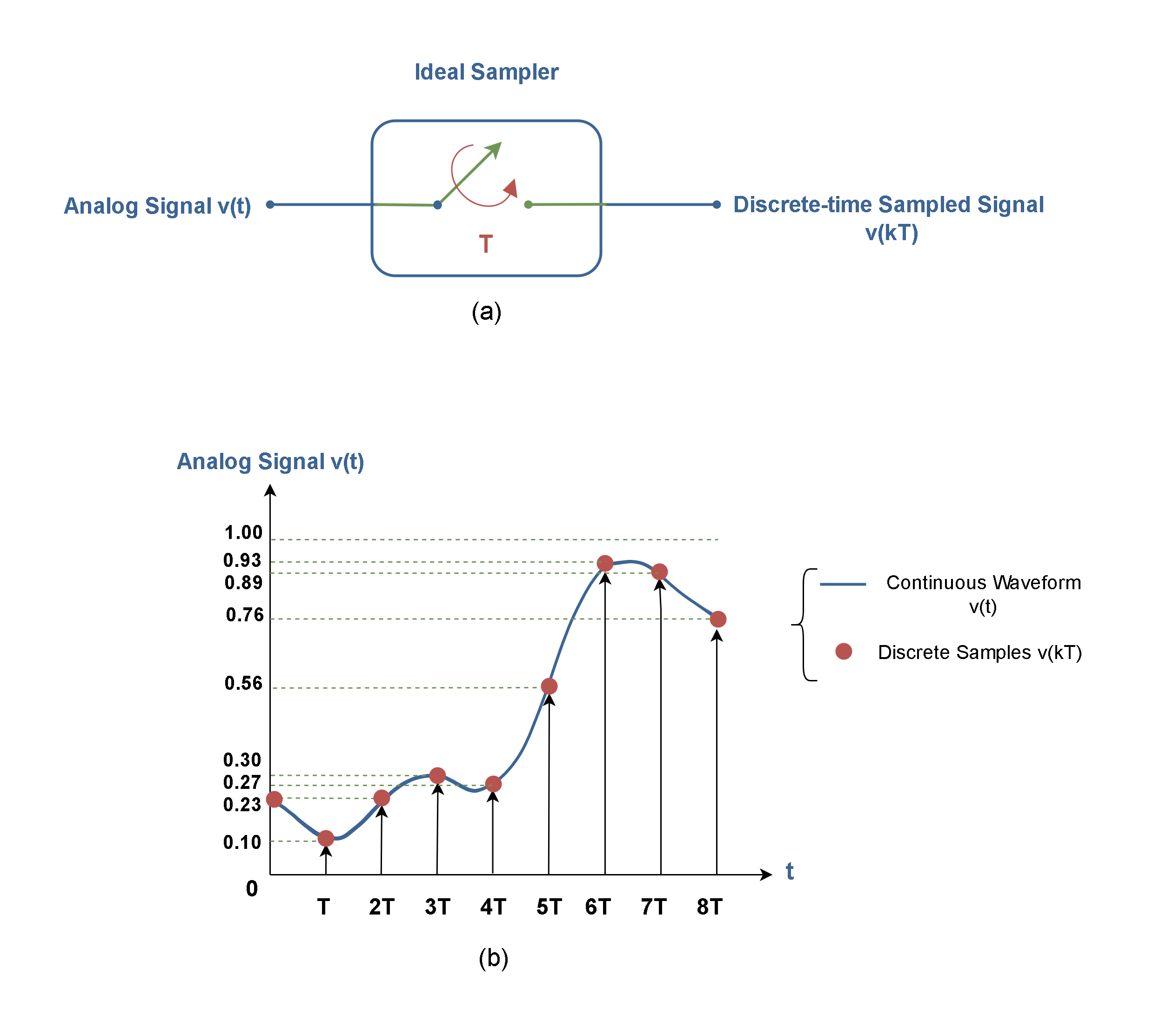
- Sample-and-hold circuit: At each tick of the sampling clock (set by the sampling frequency ), this circuit captures the instantaneous analog voltage and holds it steady.
- Quantizer: While the voltage is held constant, the quantizer compares it against a set of threshold levels and assigns the closest digital code.
The output is a stream of binary numbers, one per sample, representing the original signal in digital form.
Sampling and Conversion Process
Here's the full ADC pipeline, step by step:
- The analog input signal arrives at the sample-and-hold circuit.
- At each sampling instant (spaced apart), the circuit grabs and freezes the current voltage.
- The quantizer maps that held voltage to the nearest quantization level based on the bit depth and quantization scheme (uniform or non-uniform).
- The result is encoded as an -bit binary word and sent to the digital output.
ADC performance depends on several factors:
- Sampling rate (): must satisfy the Nyquist criterion () to avoid aliasing.
- Bit depth (): determines amplitude resolution.
- Linearity: how evenly spaced the actual quantization levels are compared to the ideal.
- Dynamic range: the ratio between the largest and smallest signals the ADC can faithfully represent, closely tied to bit depth.
Quantization Techniques
Dithering for Improved Signal Quality
Dithering adds a small amount of random noise to the analog signal before quantization. This might sound counterproductive, but it works because it randomizes the quantization error, breaking up the patterns that would otherwise cause audible or visible distortion.
Why dithering helps:
- Without dithering, quantization error can be correlated with the signal itself, producing harmonic distortion rather than random-sounding noise. Correlated distortion is far more perceptible.
- The added dither noise typically has a triangular or Gaussian distribution and is kept below one step size () in amplitude, so it doesn't significantly raise the overall noise floor.
- The result is that quantization error becomes more like white noise, which is less objectionable and can improve the effective resolution of the system.
Dithering is especially useful when working with low bit depths or low-amplitude signals where quantization steps are coarse relative to the signal.
Signal-to-Noise Ratio (SNR) Considerations
Signal-to-Noise Ratio (SNR) is the ratio of desired signal power to total unwanted noise power, expressed in decibels (dB). In a quantized system, the noise includes quantization noise plus any other sources (thermal noise, interference, etc.).
- Higher SNR = cleaner signal; lower SNR = more noise relative to the signal.
- As noted above, each additional bit of depth adds about 6 dB to the SNR contributed by quantization alone.
- Oversampling is another technique that improves SNR. By sampling at a rate much higher than the Nyquist minimum, quantization noise spreads across a wider frequency band. A digital filter then removes the out-of-band noise, effectively increasing the SNR within the band of interest. Each doubling of the oversampling ratio gains about 3 dB of SNR improvement.
- Combining dithering with oversampling and noise shaping can push quantization noise into frequency ranges where it matters less, squeezing better performance out of a given bit depth.