🔌Intro to Electrical Engineering Unit 5 Review
5.2 Mesh analysis
5.2 Mesh analysis
Unit & Topic Study Guides
Intro to Electrical Engineering
Electrical Quantities and Units
Ohm's Law: Understanding Resistance
Kirchhoff's Laws in Electrical Engineering
Circuit Analysis Techniques
Capacitance and Inductance
Transient Response: First-Order Circuits
Steady-State Sinusoidal Analysis
Semiconductor Basics in Electrical Engineering
Diodes and Circuits
BJTs: Bipolar Junction Transistors
Field-Effect Transistors in Electronics
Digital Systems Fundamentals
Boolean Algebra & Logic Gates
Combinational Logic Circuits
Sequential Logic Circuits
Signal Processing Fundamentals
Continuous-Time Signals & Systems
Fourier Series and Transforms
Sampling and Discrete-Time Signals
Z-Transforms in Discrete-Time Systems
Circuit Simulation Tools Overview
System Modeling & Analysis Tools
Case Studies in Electrical Engineering
Fundamental Concepts
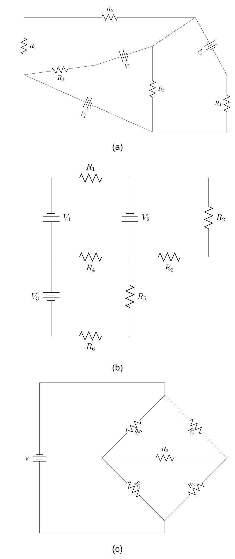
Mesh analysis is a technique for solving circuits by focusing on closed loops called meshes and applying Kirchhoff's Voltage Law (KVL) to each one. Instead of writing equations for every node or branch, you assign a current variable to each mesh and solve a smaller system of equations. For circuits with multiple interconnected loops, this approach cuts down on the math significantly.
Mesh and Loop Definitions
A loop is any closed path in a circuit that starts and ends at the same node. A mesh is a more specific thing: it's a loop that doesn't contain any other loops inside it. Think of it as the smallest possible "window" in a circuit diagram. Mesh analysis uses these innermost loops as its building blocks, which is why the distinction matters.
Kirchhoff's Voltage Law (KVL)
KVL states that the algebraic sum of all voltages around any closed loop must equal zero:
When you travel around a mesh, every voltage rise and voltage drop has to cancel out. By convention, voltage rises (like going from to through a source) are positive, and voltage drops (like current flowing through a resistor) are negative. You'll apply KVL to each mesh separately to generate your equations.
Mesh Current
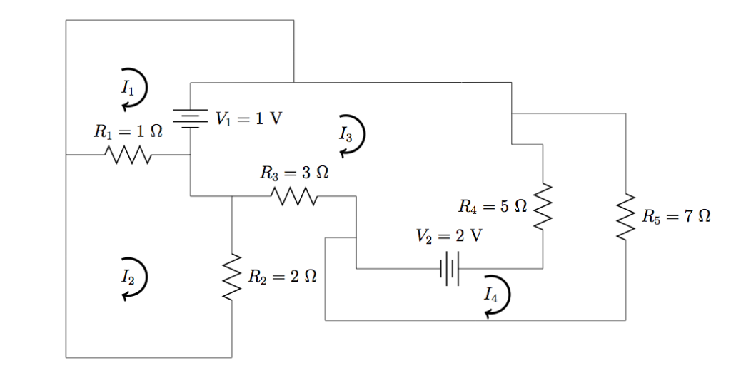
A mesh current is a hypothetical current that circulates around a single mesh. You assign one to each mesh, typically labeled , , , and so on. By convention, all mesh currents are assumed to flow clockwise. These are the unknowns you're solving for.
A branch shared by two meshes will carry the difference of the two mesh currents. For example, if meshes 1 and 2 share a resistor, the actual current through that resistor is (depending on direction). This is a detail that trips people up, so watch for it.
Circuit Elements in Mesh Equations
Branch Voltages and Resistors
The voltage drop across a resistor is found using Ohm's Law: . In mesh analysis, you express each resistor's voltage drop in terms of the mesh current(s) flowing through it.
- For a resistor only in mesh 1: the voltage drop is
- For a resistor shared between mesh 1 and mesh 2: the voltage drop (from mesh 1's perspective) is
Independent voltage sources are simpler. They contribute a known voltage value directly into the equation, positive if the mesh current flows from to through the source, negative if from to .
Resistance
Resistance (, measured in ohms, ) is the opposition to current flow. When writing mesh equations, resistors in series within the same mesh simply add together. If resistors appear in parallel within a single branch, combine them using the parallel formula before writing the mesh equation:
Analysis Techniques
Writing Mesh Equations: Step-by-Step
Here's the procedure for performing mesh analysis:
-
Identify all meshes in the circuit. Count them. The number of meshes equals the number of equations you'll need.
-
Assign a mesh current (, , etc.) to each mesh, all flowing clockwise by convention.
-
Apply KVL around each mesh. Travel clockwise around the loop. For each element you encounter:
- Resistor (only in this mesh): Write a voltage drop of .
- Resistor (shared with another mesh): Write a voltage drop of .
- Voltage source: Add or subtract its value depending on polarity relative to your travel direction.
-
Set each KVL equation equal to zero (or equivalently, set voltage drops equal to voltage rises).
-
Solve the system of equations using substitution, Gaussian elimination, or Cramer's rule.
Structure of the Equations
Each mesh equation takes a predictable form. The coefficients on the mesh currents are resistances, and the constants are the source voltages. For a two-mesh circuit, the system looks like:
Here is the shared resistor, and , are source voltages in each mesh. Notice how the shared resistor appears in both equations with opposite signs on the other mesh's current. This pattern holds for larger circuits too.
Once you've found the mesh currents, you can calculate any branch current (by adding or subtracting mesh currents through that branch) and any voltage (using Ohm's Law with the actual branch current).