🔋College Physics I – Introduction Unit 23 Review
23.12 RLC Series AC Circuits
23.12 RLC Series AC Circuits
Unit & Topic Study Guides
The Nature of Science and Physics
Kinematics
Two–Dimensional Kinematics
Force and Newton's Laws of Motion
Newton's Laws: Friction, Drag, and Elasticity
Circular Motion and Gravity
Work and Energy in Physics
Linear Momentum and Collisions
Statics and Torque
Rotational Motion & Angular Momentum
Fluid Statics
Fluid Dynamics: Biological & Medical Uses
Temperature and Gas Laws
Heat and Heat Transfer Methods
Thermodynamics
Oscillatory Motion and Waves
Physics of Hearing
Electric Charge and Fields
Electric Potential & Field
Electric Current, Resistance, and Ohm's Law
Circuits and DC Instruments
Magnetism
Electromagnetic Induction & AC Circuits
Electromagnetic Waves
Geometric Optics
Vision and Optical Instruments
Wave Optics
Special Relativity
Quantum Physics
Atomic Physics
Radioactivity and Nuclear Physics
Nuclear Physics in Medicine
Particle Physics
RLC Series AC Circuits
An RLC series circuit combines a resistor, inductor, and capacitor in a single loop driven by an AC source. Analyzing these circuits means understanding how impedance, phase angle, and resonant frequency determine the current and power behavior. These concepts show up in radio tuning, signal filtering, and wireless power transfer.
Impedance and Phase Calculations
In a DC circuit, resistance is the only thing opposing current. In an AC circuit with inductors and capacitors, you also deal with reactance, which depends on frequency. The total opposition to current in an RLC circuit is called impedance.
Impedance () combines resistance and the net reactance into a single quantity:
where:
- is resistance (in ohms), the opposition to current that dissipates energy as heat
- is inductive reactance, the opposition from an inductor:
- is capacitive reactance, the opposition from a capacitor:
- is the frequency of the AC source, is inductance, and is capacitance
Notice that increases with frequency (inductors resist rapid changes in current), while decreases with frequency (capacitors pass high-frequency signals more easily). This frequency dependence is what makes RLC circuits behave so differently at different frequencies.
Current in the circuit follows an AC version of Ohm's law:
Because impedance is always at least as large as alone, adding reactive components generally reduces the current compared to a purely resistive circuit (except at resonance, where and ).
Phase angle () tells you the timing relationship between the source voltage and the current:
- : The circuit behaves inductively. Current lags voltage (positive ).
- : The circuit behaves capacitively. Current leads voltage (negative ).
- : The circuit is purely resistive. Current and voltage are in phase ().
A helpful mnemonic: "ELI the ICE man." In an inductor (L), voltage (E) leads current (I). In a capacitor (C), current (I) leads voltage (E).
Resonant frequency () is the special frequency where , so the reactive effects cancel:
At resonance, drops to its minimum value of , and current reaches its maximum.
Power in RLC circuits:
- Average (real) power is dissipated only in the resistor:
- Inductors and capacitors store and release energy each cycle but do not dissipate power on average.
- The power factor, , describes how much of the apparent power () actually does useful work:
- At resonance, , so all the apparent power is real power. Away from resonance, the power factor drops below 1, meaning the circuit is less efficient at delivering real power.
RLC Circuit Diagram Interpretation
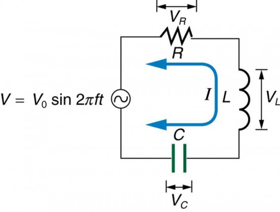
In a series RLC circuit, the resistor, inductor, capacitor, and AC source are connected end-to-end in a single loop. Because it's a series circuit, the same current flows through every component.
To analyze a circuit diagram, follow these steps:
-
Identify component values: Read off , , and from the diagram, along with the source voltage and frequency .
-
Calculate reactances: Find and .
-
Find impedance: .
-
Find current: .
-
Find phase angle: .
-
Calculate power: or equivalently .
Keep in mind that the voltage across each component can differ in both amplitude and phase. The individual voltages across , , and don't simply add up arithmetically; they add as phasors (vectors), which is why the total source voltage can actually be less than the voltage across the inductor or capacitor individually.

Resonant Frequency Applications
At resonance, impedance is minimized and current is maximized, making the circuit purely resistive. This property is useful in many technologies:
- Radio and TV tuning: By adjusting or , you change to match the frequency of a desired station. The circuit passes that frequency's signal strongly while rejecting others.
- Wireless power transfer: Systems like wireless phone chargers use resonant coupling between two RLC circuits tuned to the same frequency, maximizing energy transfer efficiency.
- Electronic filters: RLC circuits can be designed as bandpass filters (passing a narrow range of frequencies) or band-reject filters (blocking a narrow range). Audio equalizers use banks of these filters to boost or cut specific frequency ranges.
- Resonant transformers: Used in some high-voltage power systems to transfer energy efficiently at a tuned frequency, reducing losses.
Circuit Performance Characteristics
Two quantities describe how an RLC circuit behaves near resonance:
- Bandwidth is the range of frequencies (centered on ) over which the circuit response stays above a useful level, typically defined as the range where current is at least (about 70.7%) of its peak value. A narrow bandwidth means the circuit is highly selective.
- Quality factor () is a dimensionless number that measures this selectivity. A higher means a sharper resonance peak and narrower bandwidth. For a series RLC circuit, . A circuit with low resistance relative to its reactive components will have a high , meaning it rings longer and filters more sharply.
Bandwidth and are inversely related: . So a high- circuit is great for picking out a single frequency (like a radio station), while a low- circuit passes a wider range of frequencies.