🔋Electromagnetism II Unit 4 Review
4.5 Radiation pattern
4.5 Radiation pattern
Unit & Topic Study Guides
Maxwell's equations
Electromagnetic waves
Waveguides & Transmission Lines
Antennas and radiation
Electrodynamics & Special Relativity
Electromagnetic Potentials & Fields
Magnetostatics & Magnetic Materials
Electromagnetic Induction: Faraday's Law
Electromagnetic Energy & Poynting Vector
Electromagnetic Boundaries and Interfaces
Radiation pattern fundamentals
A radiation pattern describes how an antenna distributes electromagnetic energy across space. It's the primary tool for understanding where an antenna sends (or receives) power, and it directly determines an antenna's directivity, gain, and polarization characteristics.
Definition of radiation pattern
A radiation pattern is a three-dimensional plot of an antenna's radiated power (or field strength) as a function of angular direction. You typically express it in spherical coordinates using azimuth angle and elevation angle . The pattern can represent either the electric field magnitude (field pattern) or the power per unit solid angle (power pattern), with the power pattern being proportional to the square of the field pattern.
Key characteristics of radiation patterns
Every radiation pattern has a few structural features you need to recognize:
- Main lobe: the region around the direction of maximum radiation intensity. This is where the antenna concentrates most of its radiated power.
- Sidelobes: smaller lobes flanking the main lobe. These represent radiation in undesired directions and are a source of interference.
- Back lobe: the lobe pointing roughly opposite to the main lobe. The front-to-back ratio compares the main lobe peak to the back lobe peak, usually in dB.
- Nulls: angular directions where the radiated field drops to zero (or near zero). Nulls separate adjacent lobes.
Types of radiation patterns
- Omnidirectional: uniform radiation in one plane (typically azimuth) with variation in the orthogonal plane. A half-wave dipole is the classic example.
- Directional: radiation concentrated toward one or more preferred directions. A Yagi-Uda antenna produces a strong main lobe along its boom axis.
- Hemispherical: radiation primarily into one half-space. Patch (microstrip) antennas radiate mainly above the ground plane.
- Shaped: the pattern is engineered to match a specific coverage footprint, common in reflector antennas for satellite broadcasting.
Isotropic vs. anisotropic radiation
An isotropic radiator is a theoretical point source that radiates equally in all directions. No physical antenna is truly isotropic, but it serves as the universal reference: gains quoted in dBi are measured relative to this ideal. Every real antenna is anisotropic, meaning its radiation intensity varies with direction.
Radiation pattern parameters
These parameters let you quantify an antenna's performance and make meaningful comparisons between designs.
Directivity and gain
Directivity is the ratio of the peak radiation intensity to the average radiation intensity over all directions:
where is the total radiated power. Directivity tells you how well the antenna focuses energy, independent of losses.
Gain folds in the antenna's radiation efficiency :
Gain accounts for ohmic losses, impedance mismatch, and other dissipative effects. Both directivity and gain are expressed in dBi.
Beamwidth and sidelobes
- Half-power beamwidth (HPBW): the angular width of the main lobe between the two directions where power drops to half its peak value (−3 dB points). A narrower HPBW means higher directivity.
- First-null beamwidth (FNBW): the angular span between the first nulls on either side of the main lobe. FNBW is always wider than HPBW.
- Sidelobe level (SLL): the ratio (in dB) of the highest sidelobe peak to the main lobe peak. For example, a uniform linear array has a theoretical SLL of about −13.3 dB. Lower SLL means less wasted power and less interference.
Polarization of radiation patterns
Polarization describes the orientation and behavior of the electric field vector as the wave propagates:
- Linear polarization: the electric field oscillates along a fixed direction (horizontal or vertical).
- Circular polarization: the electric field vector rotates at the wave frequency with constant magnitude. It can be right-hand (RHCP) or left-hand (LHCP).
- Elliptical polarization: the general case where the field traces an ellipse. Linear and circular are special cases of elliptical.
A polarization mismatch between transmitting and receiving antennas causes signal loss. In the worst case (e.g., RHCP transmitter to LHCP receiver), the loss is total.
Radiation intensity and power density
- Radiation intensity : power radiated per unit solid angle, measured in W/sr. It's independent of distance from the antenna.
- Power density : power per unit area at a given distance , measured in W/m². In the far field, , which is the inverse-square law. Double the distance, and the power density drops by a factor of four.
Radiation pattern measurement
Accurate measurements verify that a fabricated antenna meets its design specifications. The two main approaches differ in where you place the measurement probe relative to the antenna.
Far-field measurement techniques
The far-field (Fraunhofer) region begins at a distance:
where is the antenna's largest dimension and is the operating wavelength. Beyond this distance, the angular pattern no longer changes with .
The measurement procedure:
- Mount the antenna under test (AUT) on a precision positioner.
- Place a known reference antenna (source or receive) at the required far-field distance.
- Rotate the AUT through and while recording received power at each angle.
- Perform the measurement inside an anechoic chamber (lined with RF absorbers) to suppress reflections.
Near-field measurement techniques
In the near-field (Fresnel) region, the field distribution changes with distance, so you can't directly read off the far-field pattern. Instead:
- Scan a small probe antenna across a surface close to the AUT (planar, cylindrical, or spherical geometry).
- Record amplitude and phase of the field at each sample point.
- Apply a near-field-to-far-field transformation (typically a Fourier-based algorithm) to compute the far-field pattern.
The main advantage is that you need a much smaller facility. This is especially useful for electrically large antennas where the far-field distance would be impractically large.
Antenna test ranges and anechoic chambers
- Elevated range: both the AUT and source antenna sit on tall towers so the direct path clears ground reflections.
- Slant range: the AUT is tilted so its main beam points away from the ground, reducing multipath.
- Compact range: a large parabolic reflector collimates a feed antenna's radiation into a plane wave, simulating far-field conditions at short distances indoors.
- Anechoic chambers: walls, floor, and ceiling are covered with pyramidal RF absorbers to approximate free-space conditions.
Radiation pattern plotting and visualization
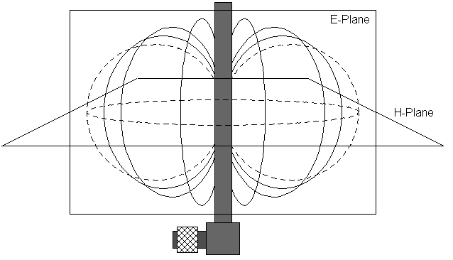
- Polar plots: show radiation intensity vs. angle in a chosen cut plane (e.g., E-plane or H-plane). These give an intuitive sense of lobe structure.
- Cartesian (rectangular) plots: plot intensity (usually in dB) on the vertical axis against angle on the horizontal axis. These make it easier to read exact sidelobe levels and null positions.
- 3D surface plots: render the full pattern, giving a complete picture of the antenna's spatial coverage.
Specialized tools like HFSS, CST, or FEKO are commonly used for simulation, visualization, and comparison against measured data.
Factors affecting radiation patterns
Several physical and electrical parameters shape an antenna's radiation pattern. Adjusting any of them changes the pattern, sometimes dramatically.
Antenna geometry and dimensions
Different antenna geometries produce fundamentally different patterns. A short dipole has a broad, donut-shaped pattern; a horn antenna produces a directive pencil beam. The key scaling parameter is the antenna's size relative to the wavelength:
- Electrically small antennas (dimensions ) have low directivity and broad patterns.
- Electrically large antennas (dimensions ) can produce narrow, high-gain beams.
Antenna aperture size and shape
The aperture is the effective area through which the antenna radiates or captures energy. Aperture antennas (horns, reflectors, lens antennas) follow a general rule: larger aperture → narrower beamwidth → higher directivity. For a circular aperture of diameter , the approximate HPBW is:
Aperture shape matters too. A circular aperture gives an axially symmetric beam, while a rectangular aperture produces different beamwidths in the E-plane and H-plane.
Antenna array configurations
Arrays combine multiple elements to achieve patterns that a single element cannot. The total pattern equals the element pattern multiplied by the array factor (pattern multiplication principle).
- Linear arrays: elements along a line produce a fan-shaped beam. Spacing and excitation weights control beamwidth and SLL.
- Planar arrays: a 2D grid of elements enables pencil beams with steering in both azimuth and elevation.
- Phased arrays: progressive phase shifts across elements steer the beam electronically without physically moving the antenna. Beam direction for a uniform linear array with spacing is set by , where is the inter-element phase shift and .

Frequency and wavelength effects
As frequency increases (wavelength decreases), a fixed-size antenna becomes electrically larger, which generally increases directivity and narrows the beam. However, the pattern shape can change significantly across a wide bandwidth. Broadband antennas like log-periodic dipole arrays are designed so that the active region scales with wavelength, maintaining a roughly consistent pattern over a wide frequency range.
Applications of radiation patterns
The choice of radiation pattern directly determines how well an antenna performs in a given system. Here are the major application areas.
Wireless communication systems
- Cellular networks: base stations use sectorized antennas (typically 120° beamwidth) to divide a cell into sectors, increasing capacity and reducing co-channel interference.
- Wi-Fi: access points commonly use omnidirectional antennas for broad indoor/outdoor coverage in WLANs.
- Point-to-point links: high-gain parabolic dishes (gains of 30–45 dBi) connect cell towers or buildings over distances of tens of kilometers.
Radar and remote sensing
- Tracking radar: phased arrays with narrow, steerable beams detect and follow targets with high angular resolution.
- Weather radar: fan-beam or pencil-beam antennas scan the atmosphere to map precipitation and wind patterns.
- Synthetic aperture radar (SAR): exploits platform motion to synthesize a large effective aperture, achieving meter-scale resolution from aircraft or satellites.
Satellite and space communications
- Geostationary satellites: shaped-beam reflector antennas tailor coverage to match continental or regional footprints.
- GPS: satellite antennas use shaped patterns to provide roughly uniform power density across the visible Earth surface.
- Deep space communication: NASA's Deep Space Network uses 34 m and 70 m Cassegrain reflectors with extremely high gain to maintain links with interplanetary spacecraft.
Biomedical imaging and therapy
- Microwave imaging: antenna arrays with controlled radiation patterns can non-invasively image breast tissue for tumor detection.
- Hyperthermia therapy: focused arrays deliver localized heating to cancerous tissue while sparing surrounding healthy tissue.
- Wireless capsule endoscopy: miniaturized omnidirectional antennas inside swallowable capsules transmit images of the gastrointestinal tract to external receivers.
Advanced topics in radiation patterns
These topics represent active research areas and increasingly practical technologies in modern antenna engineering.
Adaptive and reconfigurable radiation patterns
Adaptive antennas (smart antennas) dynamically reshape their patterns in real time. An array with adaptive beamforming can place nulls toward interferers and steer the main beam toward the desired user, all through digital signal processing of the element weights.
Reconfigurable antennas physically or electrically alter their structure to change frequency, polarization, or pattern shape. Examples include PIN-diode-switched elements, varactor-tuned patches, microfluidic antennas (liquid metal repositioned in channels), and origami-inspired foldable structures.
MIMO and diversity antenna systems
MIMO (multiple-input, multiple-output) uses multiple antennas at both ends of a link to exploit multipath propagation:
- Spatial multiplexing: sends independent data streams on different antennas simultaneously, multiplying channel capacity.
- Diversity: transmits or receives the same signal via multiple paths to combat fading.
Diversity antenna systems combine antennas with different characteristics:
- Spatial diversity: antennas separated by at least to ensure uncorrelated fading.
- Polarization diversity: orthogonally polarized antennas reduce polarization mismatch losses in scattering environments.
Metamaterial-based radiation pattern control
Metamaterials are engineered structures with electromagnetic properties (e.g., negative refractive index) not found in nature. Applied to antennas, they enable:
- Leaky-wave antennas: metamaterial transmission lines radiate as guided waves leak energy, with beam direction controlled by frequency or structural tuning.
- Cloaking: metamaterial shells reduce an antenna's scattering cross-section, minimizing its effect on nearby antennas.
- Metasurfaces: thin, planar arrays of sub-wavelength elements that control phase and amplitude of transmitted or reflected waves. Huygens' metasurfaces can synthesize nearly arbitrary far-field patterns from a simple feed.
Computational methods for radiation pattern analysis
Numerical methods solve Maxwell's equations for antenna structures too complex for closed-form solutions:
- Method of Moments (MoM): discretizes the antenna surface into segments, solves integral equations for surface currents, then computes the radiated fields. Well-suited for wire and planar structures.
- Finite-Difference Time-Domain (FDTD): steps through time on a spatial grid, naturally handling broadband and transient problems.
- Finite Element Method (FEM): divides the volume into tetrahedral elements, solving for fields with high geometric flexibility. Good for complex 3D structures.
Optimization algorithms automate the search for antenna designs meeting target pattern specifications:
- Genetic algorithms (GA): evolve a population of candidate designs through selection, crossover, and mutation.
- Particle swarm optimization (PSO): candidate solutions move through the design space, sharing information to converge on optimal configurations.
- Neural networks: trained on simulation data, they can rapidly predict radiation patterns for new geometries or perform inverse design (specify a desired pattern, get an antenna geometry).