🔋Electromagnetism II Unit 8 Review
8.4 Eddy currents
8.4 Eddy currents
Unit & Topic Study Guides
Maxwell's equations
Electromagnetic waves
Waveguides & Transmission Lines
Antennas and radiation
Electrodynamics & Special Relativity
Electromagnetic Potentials & Fields
Magnetostatics & Magnetic Materials
Electromagnetic Induction: Faraday's Law
Electromagnetic Energy & Poynting Vector
Electromagnetic Boundaries and Interfaces
Induced EMF from Changing Magnetic Flux
Eddy currents arise from the same principle behind all electromagnetic induction: a changing magnetic flux through a conductor produces an electromotive force (EMF). Before diving into eddy currents specifically, it's worth grounding yourself in the basics.
An induced EMF appears whenever the magnetic flux through a conducting region changes over time. That change can come from three sources: a shifting magnetic field strength, a change in the area exposed to the field, or a rotation of the conductor relative to the field. Faraday's law and Lenz's law together determine how large the induced EMF is and which direction the resulting current flows.
Faraday's Law of Induction
Faraday's law quantifies the induced EMF. It says the EMF around a conducting loop equals the negative rate of change of magnetic flux through that loop:
where is the induced EMF, is the magnetic flux, and is time. The negative sign encodes Lenz's law: the induced EMF always acts in a direction that opposes the flux change that created it.
For a coil with turns, this generalizes to . This form matters when you analyze transformers and inductors later.
Lenz's Law and Direction of Induced Currents
Lenz's law tells you which way the induced current flows. The current always creates its own magnetic field that opposes the change in the original flux. If the external flux through a loop is increasing, the induced current flows in the direction that produces a field opposing that increase.
This isn't arbitrary. Lenz's law is a direct consequence of energy conservation. If the induced current reinforced the flux change instead of opposing it, you'd get runaway current generation from nothing, violating conservation of energy. The induced current must do work against the change, and that work comes from whatever is driving the flux change (a moving magnet, a changing current in a nearby coil, etc.).
Eddy Currents in Conductors
Now for the main topic. Eddy currents are loops of current induced inside a bulk conductor (not just a wire loop) when it's exposed to a changing magnetic field. Unlike current in a circuit that follows a defined wire path, eddy currents swirl through the volume of the conductor in closed loops perpendicular to the applied field. They obey the same Faraday/Lenz principles, but because the conductor is an extended piece of material, the current paths can be complex.
These currents dissipate energy as resistive (Joule) heating, which is sometimes useful and sometimes a problem you need to minimize.
Generation of Eddy Currents
The mechanism is straightforward:
- A changing magnetic flux passes through a region of a bulk conductor.
- The changing flux induces an EMF throughout that region (Faraday's law).
- Because the material is conductive, the EMF drives charge carriers (electrons) into circulating paths.
- These circulating paths form closed current loops within the conductor.
The magnitude of the eddy currents depends on the rate of flux change () and the electrical conductivity of the material. High conductivity and rapid flux changes produce strong eddy currents.
Factors Affecting Eddy Current Strength
Several factors control how large the eddy currents become:
- Magnetic field strength: Stronger fields mean greater flux, so changes produce larger induced EMFs.
- Frequency of the changing field: Higher frequencies mean faster flux changes, directly increasing and thus the induced EMF.
- Electrical conductivity of the material: Highly conductive materials like copper ( S/m) and aluminum support much larger eddy currents than resistive materials.
- Geometry and size of the conductor: Larger cross-sectional areas perpendicular to the field allow bigger current loops, which carry more current. A thin sheet produces weaker eddy currents than a thick slab.
Skin Effect and Current Distribution
At high frequencies, eddy currents don't distribute evenly through the conductor. Instead, they concentrate near the surface. This is the skin effect.
The current density falls off exponentially with depth from the surface. The characteristic length scale for this decay is the skin depth:
where is the angular frequency of the field, is the magnetic permeability of the conductor, and is its electrical conductivity. At a depth of one skin depth, the current density has dropped to (about 37%) of its surface value.
For copper at 60 Hz, mm. At 1 MHz, it drops to about 0.066 mm. This matters because the effective cross-section carrying current shrinks at high frequency, increasing the AC resistance and power losses.
Applications of Eddy Currents
Eddy currents aren't just a nuisance. Several technologies deliberately exploit them.
Electromagnetic Braking Systems
Electromagnetic brakes use eddy currents to slow a moving conductor without any physical contact. Here's how they work:
- A conductive disc or drum rotates through a magnetic field (from permanent magnets or electromagnets).
- The relative motion between the conductor and the field induces eddy currents in the disc.
- By Lenz's law, these eddy currents create a magnetic field that opposes the motion.
- The result is a braking force proportional to the speed of the conductor.
This type of brake is smooth, wear-free, and easy to control by adjusting the magnetic field strength. You'll find electromagnetic brakes on high-speed trains, roller coasters, heavy trucks (as retarders), and wind turbines.
One key feature: the braking force vanishes at zero speed, so electromagnetic brakes alone can't hold a vehicle stationary. They're always paired with friction brakes for a complete stop.

Induction Heating and Melting
Induction heating turns eddy current losses into a feature. A coil carrying high-frequency AC generates a rapidly alternating magnetic field. When a conductive workpiece is placed inside or near the coil:
- The alternating field induces strong eddy currents in the workpiece.
- The material's electrical resistance converts the eddy current energy into heat ().
- The skin effect concentrates the heating near the surface, which is useful for surface hardening of metals.
Industrial uses include metal hardening, brazing, welding, and melting. Induction cooktops use the same principle: the coil beneath the ceramic surface induces eddy currents directly in the ferromagnetic cookware, heating the pot rather than the stovetop.
Eddy Current Testing for Defects
Eddy current testing (ECT) is a non-destructive evaluation technique for finding surface and near-surface flaws in conductive materials.
- A probe containing a coil is brought near the test specimen.
- The coil's AC current generates a localized alternating magnetic field.
- This field induces eddy currents in the specimen.
- If the material is uniform, the eddy currents flow in predictable patterns.
- Defects (cracks, voids, corrosion, thickness variations) disrupt the eddy current flow.
- The disrupted currents change the impedance of the probe coil, which is measured and analyzed.
ECT is widely used in aerospace (inspecting turbine blades, fuselage skins), automotive manufacturing, and pipeline inspection. It's fast, requires no contact with the surface, and can detect sub-surface flaws within a few skin depths.
Minimizing Unwanted Eddy Currents
In devices like transformers, motors, and generators, eddy currents in the magnetic core waste energy as heat. Reducing these losses is a major engineering concern.
Laminated Cores vs. Solid Cores
The most common strategy is lamination. Instead of using a solid block of magnetic material for the core, you stack thin sheets (laminations) of silicon steel, each coated with a thin insulating layer.
The insulation between layers breaks up the eddy current paths. In a solid core, eddy currents can flow in large loops across the entire cross-section. In a laminated core, each lamination confines the currents to a much smaller loop. Since power loss scales with the square of the loop area, thinner laminations dramatically reduce losses.
Typical lamination thickness is 0.25 to 0.5 mm for power-frequency (50/60 Hz) transformers. Higher-frequency applications use even thinner laminations.
Ferrite Materials for High Frequencies
At frequencies above a few hundred kHz, even thin steel laminations can't suppress eddy currents effectively. Ferrite cores are used instead.
Ferrites are ceramic compounds (typically containing iron oxide mixed with manganese, zinc, or nickel oxides). Their key property is very high electrical resistivity, on the order of to , compared to about for silicon steel. This high resistivity inherently suppresses eddy current formation.
Ferrites are standard in high-frequency transformers, switch-mode power supplies, RF inductors, and EMI suppression components (those cylindrical lumps on cable ends are often ferrite chokes).
Design Considerations for Reducing Eddy Losses
Beyond material choices, several design strategies help:
- Conductor geometry: Use thin, flat conductors or stranded wires to reduce the cross-sectional area available for eddy current loops.
- Higher-resistivity alloys: Materials like nichrome or manganin limit eddy current magnitude through their inherently high resistivity.
- Conductor orientation: Aligning conductors parallel to the magnetic field lines minimizes the flux change through their cross-section, reducing the induced EMF.
- Magnetic shielding and flux guides: Materials like mu-metal can redirect stray flux away from regions where eddy currents are undesirable.
Eddy Currents in Transformers and Inductors
Transformers and inductors are especially susceptible to eddy current losses because their cores are deliberately designed to carry large, time-varying magnetic flux.
Impact on Efficiency and Power Loss
Eddy current losses in the core (part of what's called core loss, alongside hysteresis loss) dissipate power as heat. The eddy current power loss per unit volume in a laminated core can be estimated as:
where is the peak flux density, is the frequency, is the lamination thickness, and is the resistivity of the core material. Two things stand out: loss scales with and with . This is why eddy current losses become severe at high frequencies and why you need to switch from steel laminations to ferrites as frequency increases.
In the windings, eddy currents also cause losses through the skin effect and the proximity effect (where the magnetic field from adjacent turns induces additional eddy currents in a given turn).
Techniques for Mitigating Eddy Currents
A summary of the main mitigation approaches for transformers and inductors:
- Laminated cores: Thin, insulated laminations for power-frequency operation.
- Grain-oriented silicon steel: The crystal structure is aligned to provide high permeability along the flux direction with low core losses.
- Ferrite cores: For frequencies above roughly 100 kHz.
- Litz wire: Stranded wire where each thin strand is individually insulated. The strands are woven so that each one occupies every position in the bundle equally, canceling out skin effect and proximity effect losses.
- Shielding and flux control: Magnetic shielding and careful core geometry to minimize stray fields that would induce eddy currents in nearby conductors or enclosures.
Numerical Methods for Eddy Current Analysis
Real-world eddy current problems rarely have simple analytical solutions. Complex geometries, nonlinear materials, and transient conditions require numerical methods.
Finite Element Method (FEM)
FEM is the workhorse of computational electromagnetics for eddy current problems.
- The problem domain (the conductor, surrounding air, magnetic cores) is divided into a mesh of small elements (triangles in 2D, tetrahedra in 3D).
- Maxwell's equations are solved approximately over each element, with continuity enforced at element boundaries.
- The method assembles a large system of linear (or nonlinear) equations and solves for the field quantities (magnetic vector potential, current density, etc.) at each node.
FEM handles complex geometries, inhomogeneous materials, and nonlinear B-H curves well. It's the standard approach in commercial tools like ANSYS Maxwell and COMSOL Multiphysics. The trade-off is computational cost: 3D transient eddy current simulations with fine meshes can be very demanding.
Boundary Element Method (BEM)
BEM takes a different approach. Instead of meshing the entire volume, it only discretizes the boundaries (surfaces) of the problem domain.
- The governing equations are reformulated as boundary integral equations.
- Only the surfaces need to be meshed, which reduces the problem dimensionality by one.
- This produces smaller system matrices than FEM for equivalent problems.
BEM is particularly well-suited for problems with large open (unbounded) regions, like an eddy current probe scanning over a test specimen in free space. It's also efficient for problems with homogeneous, linear materials. However, BEM struggles with nonlinear materials and inhomogeneous domains, where FEM is more flexible.
Eddy Currents in Moving Conductors
When a conductor physically moves through a static magnetic field (rather than sitting in a time-varying field), eddy currents still arise because the flux through any region of the conductor is changing due to the motion.
Motional EMF and Lorentz Force
The motional EMF for a conductor element moving with velocity through a field is:
For a straight conductor of length moving perpendicular to a uniform field, this simplifies to .
The eddy currents driven by this EMF then experience a Lorentz force:
where is the current density. By Lenz's law, this force opposes the motion, producing magnetic drag.
Eddy Current Flow Patterns
The geometry of the conductor and the field orientation determine the eddy current patterns:
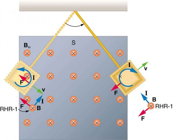
- Flat plate moving through a localized field: Eddy currents form closed loops in the plane of the plate. Current density is highest near the edges of the field region and decreases away from it.
- Rectangular conductor in a uniform field: Currents circulate in planes perpendicular to the field, with the highest density near the conductor edges.
- Cylindrical conductor rotating in a field: Eddy currents form circular loops in planes perpendicular to the rotation axis.
These flow patterns can produce striking effects. A spinning conductive top (like the Levitron) can levitate above a magnetic base because the eddy currents induced by its rotation create a repulsive force that balances gravity.
Magnetic Damping and Levitation
The interaction between eddy currents and magnetic fields produces two practically important phenomena: damping and levitation.
Eddy Current Damping Mechanisms
When a conductor moves through a magnetic field, the eddy current drag force is proportional to the conductor's velocity. This velocity-dependent force is exactly the behavior of a viscous damper, making eddy current damping useful for vibration suppression.
Applications include:
- Eddy current brakes on trains and industrial equipment (discussed above).
- Vibration dampers for sensitive instruments. A conductive plate attached to the vibrating structure moves through a magnetic field, and the induced eddy currents dissipate the kinetic energy as heat.
- Analog meter damping. The needle in a galvanometer is attached to a conductive frame that moves in a magnetic field. Eddy currents in the frame damp oscillations so the needle settles quickly to the correct reading.
Maglev Trains and Magnetic Bearings
Magnetic levitation systems use the repulsive forces from eddy currents (among other electromagnetic effects) to achieve contactless suspension.
Electrodynamic suspension (EDS) maglev systems work as follows:
- Superconducting magnets on the train create strong static fields.
- As the train moves, these fields induce eddy currents in conductive guideway coils or plates.
- The eddy currents produce repulsive forces that lift the train off the guideway.
- Faster motion means stronger eddy currents and greater lift, so EDS systems need wheels for low-speed operation until sufficient speed is reached.
This is distinct from electromagnetic suspension (EMS), which uses actively controlled electromagnets to create attractive forces and doesn't rely on eddy currents for lift.
Magnetic bearings use similar principles to levitate rotating shafts. Eddy current effects provide passive damping and stiffness, often combined with active electromagnetic control. Benefits include zero mechanical friction, no lubrication requirements, and the ability to operate at very high speeds or in vacuum environments.