⚾️Honors Physics Unit 20 Review
20.2 Motors, Generators, and Transformers
20.2 Motors, Generators, and Transformers
Unit & Topic Study Guides
What is Physics?
Motion in One Dimension
Forces and Newton’s Laws of Motion
Motion in Two Dimensions
Circular and Rotational Motion
Newton's Law of Gravitation
Momentum
Work, Energy, and Simple Machines
Thermal Energy, Heat, and Work
Thermodynamics
Waves and Their Properties
Sound
Mirrors and Lenses
Diffraction and Interference
Static Electricity
Electrical Circuits
Magnetism
The Quantum Nature of Light
The Atom
Electric Motors, Generators, and Transformers
Electric motors, generators, and transformers convert energy between electrical and mechanical forms using electromagnetic principles. These three devices are responsible for generating, transmitting, and using nearly all the electrical power in the modern world.

Principles of Electromagnetic Devices
All three devices rely on the relationship between magnetic fields and electric currents, but each one does something different with that relationship.
Electric motors convert electrical energy into mechanical energy. A current-carrying wire placed in a magnetic field experiences a force (recall ). Inside a motor, this force creates torque that spins a rotating component called the rotor, while the stator remains stationary and provides the magnetic field. DC motors run on direct current, while AC motors run on alternating current. AC motors come in two main types: induction motors (by far the most common) and synchronous motors.
Generators do the reverse: they convert mechanical energy into electrical energy. Something external (a turbine, an engine, a hand crank) spins the rotor through a magnetic field, and by Faraday's law of electromagnetic induction, this changing magnetic flux through the coils induces an EMF. AC generators (alternators) produce alternating current and are used in virtually all power plants. DC generators (dynamos) produce direct current but are far less common today.
Notice the symmetry: a motor and a generator are structurally almost identical. The difference is which form of energy you put in and which you get out.
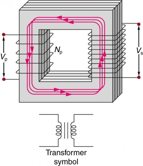
Transformers change the voltage level of an AC supply using mutual induction. Two coils of wire (primary and secondary) are wrapped around a shared iron core. An alternating current in the primary coil creates a changing magnetic flux through the core, which induces a voltage in the secondary coil.
- A step-up transformer increases voltage while decreasing current (fewer turns on the primary, more on the secondary).
- A step-down transformer decreases voltage while increasing current (more turns on the primary, fewer on the secondary).
Transformers only work with AC because they require a changing magnetic flux to induce a voltage. A steady DC current would produce a constant flux, and no voltage would be induced in the secondary coil.

Commercial Power Systems
Getting electricity from a power plant to your wall outlet involves three stages: generation, transmission, and distribution.
Power generation happens at power plants, where some energy source spins a turbine connected to a generator:
- Fossil fuel plants burn coal, natural gas, or oil to produce steam that drives a turbine.
- Nuclear plants use heat from fission reactions to produce steam.
- Hydroelectric dams use falling water to spin turbines directly.
- Wind turbines and geothermal plants also drive generators mechanically.
- Solar panels are the exception: they convert sunlight directly into electricity using the photovoltaic effect, with no generator involved.
Power transmission moves electricity over long distances. This is where transformers become essential. At the power plant, step-up transformers boost the voltage to hundreds of kilovolts (often 230 kV to 765 kV). Why? Because power lost to resistance in the wires equals . By stepping voltage up, you step current down proportionally, which dramatically reduces resistive losses over long transmission lines.
Power distribution delivers electricity to homes and businesses. At substations near populated areas, step-down transformers reduce the voltage in stages. The final distribution transformers (the cylindrical cans you see on utility poles) bring the voltage down to 120/240 V for household use in the US.
The entire interconnected network of generation, transmission, and distribution is called the power grid.
Electromagnetic Principles and Efficiency
No energy conversion is perfectly efficient. In real motors, generators, and transformers, some energy is always lost:
- Resistive (copper) losses: Current flowing through the wire coils generates heat ().
- Core (iron) losses: The changing magnetic field in the iron core causes energy loss through eddy currents and hysteresis.
- Mechanical losses: Friction and air resistance in motors and generators.
Well-designed large transformers can reach efficiencies above 99%, which is why they're so effective for power transmission. Motors and generators typically have lower efficiencies due to additional mechanical losses.
The key insight behind high-voltage transmission bears repeating: for a given amount of power (), increasing voltage means decreasing current, and since resistive power loss depends on , even a modest reduction in current produces a large reduction in wasted energy.
Transformer Equation Calculations
The transformer equation for an ideal (100% efficient) transformer is:
where:
- and are the primary and secondary voltages
- and are the number of turns in the primary and secondary coils
- and are the primary and secondary currents
Notice that the current ratio is inverted compared to the voltage and turns ratios. This reflects conservation of energy: if voltage goes up, current must come down (and vice versa), since in an ideal transformer.
How to solve transformer problems:
- Identify which quantities you know (voltages, turns, or currents) and which you need to find.
- Calculate the turns ratio .
- Set up the appropriate part of the transformer equation and solve for the unknown.
Example: A transformer has 500 turns on the primary coil and 1000 turns on the secondary coil. The primary voltage is 120 V. Find the secondary voltage.
- Find the turns ratio:
- Apply the transformer equation:
- Substitute:
- Solve:
Since , this is a step-up transformer, and the secondary voltage (240 V) is greater than the primary voltage (120 V). If the primary current were 2 A, you could find the secondary current using , giving . Voltage doubled, current halved, and power is conserved.