Modulation and demodulation are core techniques that allow information to be transmitted over long distances by encoding data onto a carrier signal, then extracting it at the receiver. Without modulation, you'd need impractically large antennas and couldn't share the frequency spectrum among multiple users.
Fourier analysis is what makes these techniques understandable and designable. By moving into the frequency domain, you can see exactly how modulation reshapes a signal's spectrum, determine bandwidth requirements, and build demodulation systems that cleanly recover the original information.
Modulation Techniques
Principles of Amplitude, Frequency, and Phase Modulation
Modulation works by varying a parameter of a high-frequency carrier signal according to the instantaneous value of a lower-frequency modulating signal (the information you want to send). Which parameter you vary defines the type of modulation.
- Amplitude Modulation (AM) varies the carrier's amplitude in proportion to the modulating signal while keeping frequency constant. This is the basis of AM radio broadcasting.
- Frequency Modulation (FM) varies the carrier's frequency in proportion to the modulating signal while keeping amplitude constant. FM radio uses this for higher-fidelity audio.
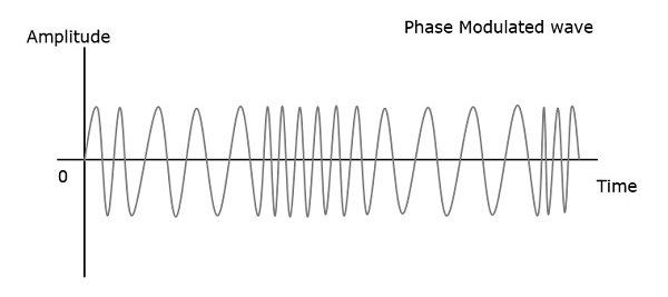
- Phase Modulation (PM) varies the carrier's phase in proportion to the modulating signal while keeping amplitude and frequency constant. PM is widely used in satellite communication and forms the basis of many digital schemes.
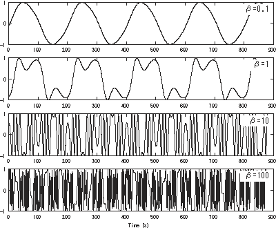
The modulation index quantifies how much the modulated parameter deviates relative to the unmodulated carrier. A higher modulation index means a greater extent of variation, which directly affects bandwidth and signal quality.
Mathematical Representation of Modulation Techniques
Each modulation type has a standard mathematical form built from trigonometric functions. For FM and PM, Bessel functions appear when you expand the expressions into their spectral components.
AM signal:
where is the modulating signal, is the carrier amplitude, and is the carrier frequency. The term means the carrier amplitude scales up and down with the message. If the peak of exceeds 1, you get overmodulation, which distorts the envelope and makes clean demodulation impossible.
FM signal:
where is the frequency sensitivity (Hz per volt). Notice the integral: the instantaneous frequency is , so the message signal directly controls how fast the phase accumulates.
PM signal:
where is the phase sensitivity (radians per volt). Here the message directly shifts the instantaneous phase rather than frequency. Comparing the FM and PM expressions, you can see that FM of a message is equivalent to PM of its integral .
Modulation and Demodulation with Fourier Transform
Fourier Analysis of Modulated Signals
The Fourier transform lets you see what modulation actually does to a signal's spectrum.
For AM, multiplying the carrier by the message corresponds to convolution in the frequency domain. The result is that the message spectrum gets shifted to center around , creating an upper sideband (above ) and a lower sideband (below ). The carrier itself appears as an impulse at . This is why AM is sometimes called "double-sideband" modulation: both sidebands carry the same information.
For FM and PM, the spectral picture is more complex. The frequency-shift property of the Fourier transform helps explain the carrier shift, but because FM/PM involve nonlinear operations on the phase, the resulting spectrum contains the carrier plus an infinite series of sidebands spaced at multiples of the modulating frequency. The amplitudes of these sidebands are given by Bessel functions of the first kind, , where is the modulation index.
Demodulation Techniques using Fourier Transform
Demodulation reverses the modulation process to recover . Each modulation type has a corresponding approach:
- AM envelope detection: The modulating signal is encoded in the envelope (outline of the peaks) of the AM waveform. A simple rectifier followed by a low-pass filter extracts this envelope. In Fourier terms, the low-pass filter removes the high-frequency carrier components and retains only the baseband message spectrum.
- FM frequency discrimination: The goal is to measure the instantaneous frequency deviation, which is proportional to . A frequency discriminator (or differentiator followed by an envelope detector) converts frequency variations into amplitude variations, then extracts the message. In the frequency domain, differentiation corresponds to multiplying by , which converts the FM signal into an AM-like signal that can then be envelope-detected.
- PM phase detection: The instantaneous phase deviation is measured to recover . Phase-locked loops (PLLs) are commonly used, tracking the carrier phase and outputting the deviation as the demodulated signal.
In all cases, the inverse Fourier transform provides the conceptual bridge from the filtered frequency-domain result back to the recovered time-domain message.
Spectral Characteristics of Modulated Signals
Bandwidth and Spectral Efficiency
The bandwidth a modulated signal occupies depends heavily on which modulation technique you use.
- AM bandwidth: Equal to twice the highest frequency component of the modulating signal, , where is the message bandwidth. For example, AM voice radio with audio up to 5 kHz occupies 10 kHz of bandwidth centered on the carrier.
- FM/PM bandwidth: Depends on both the modulation index and the message bandwidth. Higher modulation indices spread energy across more sidebands, increasing bandwidth. Carson's bandwidth rule gives a practical approximation:
where is the maximum frequency deviation and is the highest modulating frequency. For commercial FM radio, kHz and kHz, giving kHz. This is why FM stations are spaced 200 kHz apart.
Spectral efficiency, measured in bits per second per Hertz (bps/Hz), quantifies how well a modulation scheme uses available bandwidth. Higher-order digital schemes like 64-QAM achieve higher spectral efficiency (up to 6 bps/Hz) by packing more bits per symbol, but they demand better signal quality to work reliably.
Trade-offs in Modulation Techniques
No single modulation technique wins on every metric. The main trade-offs are:
- AM is simple and cheap to implement but wastes power (much of it goes into the carrier, not the sidebands carrying information) and is more vulnerable to noise.
- FM and PM provide better noise immunity and audio quality because amplitude noise doesn't corrupt the frequency/phase information. The cost is wider bandwidth.
- Digital schemes like PSK and QAM achieve higher spectral efficiency, but receivers are more complex and performance degrades more sharply with channel impairments like multipath fading.
The fundamental trade-off: you can exchange bandwidth for noise performance (FM uses more bandwidth but resists noise better), or exchange complexity for spectral efficiency (QAM packs more data per Hz but needs sophisticated receivers).
Noise and Distortion in Modulation
Effects of Noise on Modulated Signals
Noise degrades signal quality during both transmission and reception. The most commonly modeled noise type is additive white Gaussian noise (AWGN), which has a flat power spectral density across all frequencies and a Gaussian amplitude distribution. Thermal noise in electronic components is a primary source.
The signal-to-noise ratio (SNR), typically expressed in decibels (dB), measures how much stronger the desired signal is compared to the noise floor. Higher SNR means cleaner reception.
How noise affects each modulation type differs significantly:
- AM signals are highly susceptible because noise adds directly to the amplitude, which is exactly where the information lives. Any amplitude fluctuation from noise corrupts the message.
- FM and PM signals are more robust because the information is in frequency/phase, not amplitude. Amplitude noise can be removed by a limiter before demodulation. FM also exhibits a capture effect: when two signals occupy the same frequency, the stronger one suppresses the weaker one rather than both mixing together. This is why FM radio tends to either work clearly or cut out entirely, rather than producing the overlapping-station effect common in AM.
Distortion and Mitigation Techniques
Distortion arises from nonlinearities in transmitters, receivers, or the channel itself. For example, amplifier saturation introduces harmonics and intermodulation products that weren't in the original signal.
Several techniques combat noise and distortion:
- Pre-emphasis and de-emphasis filtering: Used in FM radio, pre-emphasis boosts high-frequency components of the message before transmission (where they'd otherwise be buried in noise), and de-emphasis at the receiver restores the original spectral balance. This improves high-frequency SNR without increasing overall power.
- Error correction coding: In digital systems, redundant bits are added so the receiver can detect and correct errors caused by noise. Forward error correction (FEC) codes like convolutional codes and turbo codes are standard in modern systems.
- Adaptive equalization: The receiver dynamically adjusts filter coefficients to compensate for changing channel conditions. Adaptive filters estimate the channel response and invert its distortion effects, which is critical in mobile and wireless communication where the channel varies over time.
- Diversity techniques: Using multiple antennas, frequencies, or time slots to transmit the same information reduces the chance that noise or fading corrupts all copies simultaneously.