⚡Electrical Circuits and Systems I Unit 2 Review
2.2 Ohm's Law and Resistance
2.2 Ohm's Law and Resistance
Unit & Topic Study Guides
Intro to Electrical Circuits
Basic Concepts and Laws
Resistive Circuits
Circuit Analysis Techniques
Operational Amplifiers
Capacitors and Inductors in Circuit Analysis
First–Order Circuits
Second–Order Circuits
Sinusoidal Steady-State Analysis
AC Power Analysis
Magnetic Coupling in Circuits
Ohm's Law is the cornerstone of electrical circuit analysis. It links voltage, current, and resistance into one simple relationship that governs how electricity flows through components. Nearly every circuit analysis technique you'll encounter builds on this foundation.
Resistance, the opposition to current flow, is shaped by material properties, geometry, and environmental factors. Understanding resistance and its inverse, conductance, gives you the tools to predict and control electrical behavior across a wide range of applications.
Ohm's Law and its Equation
Mathematical Representation and Principles
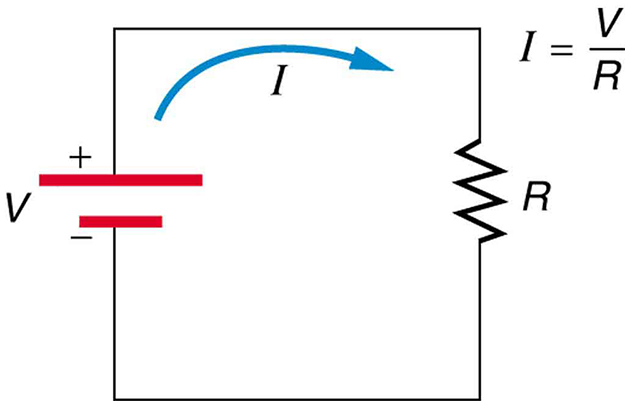
Ohm's Law states that the voltage across a resistor is directly proportional to the current through it, with resistance as the proportionality constant:
where is voltage in volts (V), is current in amperes (A), and is resistance in ohms (Ω). You can rearrange this into two other useful forms:
- (find current when you know voltage and resistance)
- (find resistance when you know voltage and current)
A few things to keep in mind: Ohm's Law assumes constant temperature and applies to linear (ohmic) resistors, meaning components where the V-I relationship is a straight line through the origin. Many common components behave this way, including standard resistors, heating elements, and incandescent filament wires (over limited ranges). It does not apply to non-linear devices like diodes and transistors, where the V-I curve is not a straight line.
Applications and Limitations
- Used to analyze simple circuits and determine unknown voltage, current, or resistance values
- Essential for designing and troubleshooting electrical systems, from household wiring to electronic devices
- Provides the foundation for more advanced techniques like Kirchhoff's Laws and nodal/mesh analysis
- Becomes limited at high frequencies, where parasitic capacitance and inductance matter, or at extreme temperatures
- Does not accurately describe certain materials like superconductors (which have zero resistance below a critical temperature) or ionized gases
Calculating Electrical Values
Using Ohm's Law for Basic Calculations
When solving problems, pick the form of Ohm's Law that isolates the unknown quantity:
- Find resistance: A 100 V source drives 2 A through a component.
- Find voltage: 3 A flows through a 20 Ω resistor.
- Find current: 12 V is applied across a 4 Ω resistor.
You can apply Ohm's Law to individual components or to entire sections of a circuit, as long as you use the voltage across and the current through that specific element or section.
Always keep your units consistent. For small or large quantities, use standard SI prefixes: milliamps (mA) for small currents, kilohms (kΩ) or megohms (MΩ) for large resistances, and so on. Converting to base units before plugging into the equation helps avoid mistakes.
Advanced Applications and Considerations
- Combine Ohm's Law with the power equation for fuller circuit analysis. Substituting gives you and , both very useful.
- In series circuits, use Ohm's Law to find the voltage drop across each component. The drops must sum to the source voltage.
- In parallel circuits, each branch sees the same voltage. Use per branch to find how current distributes.
- In AC circuits, Ohm's Law still applies, but you replace simple resistance with complex impedance , giving .
- Practical design tasks like wire sizing and component selection rely heavily on Ohm's Law to ensure safe current levels and acceptable voltage drops.
Resistance vs Conductance

Fundamental Relationship and Units
Conductance () is the reciprocal of resistance:
The unit of conductance is the siemens (S), which equals (the older term "mho" means the same thing). The relationship is inversely proportional, so:
- A 1000 Ω resistor has a conductance of 0.001 S (1 mS)
- A 1 Ω resistor has a conductance of 1 S
Think of resistance as how much a component opposes current, and conductance as how easily it permits current. They carry the same information, just expressed from opposite perspectives.
Applications in Circuit Analysis
Conductance shines in parallel circuit analysis. When resistors are in parallel, their conductances add directly:
This is often simpler than working with the reciprocal-of-reciprocals formula for parallel resistance. By contrast, resistances add directly in series:
Conductance notation is also common in semiconductor physics, filter design, and transmission line analysis, where parallel paths dominate the math.
Factors Affecting Resistance
Material Properties and Geometry
The resistance of a uniform conductor depends on three things: its length, its cross-sectional area, and the material it's made of. The relationship is:
where is the resistivity of the material (an intrinsic property, measured in Ω·m), is the conductor length, and is its cross-sectional area.
- Length: Doubling the length doubles the resistance. Current has more material to push through.
- Cross-sectional area: Halving the area doubles the resistance. There's less room for charge carriers to flow.
- Resistivity: Depends on the material itself. Copper has very low resistivity (~), while rubber is astronomically high.
- Impurities and crystal defects scatter charge carriers, increasing resistance.
- In semiconductors, doping (adding controlled impurities like phosphorus into silicon) can change resistivity by many orders of magnitude.
- Conductor geometry matters too. A tightly coiled wire has a different effective resistance at high frequencies than the same wire stretched straight, due to inductance effects.
Environmental and External Factors
- Temperature is the biggest external factor. For most metals, resistance increases with temperature. This is described by a positive temperature coefficient.
- Some materials, like carbon and most semiconductors, have a negative temperature coefficient, meaning their resistance decreases as temperature rises (more charge carriers become available).
- The linear approximation for temperature dependence is , where is the temperature coefficient of resistance.
- Mechanical stress changes resistance slightly. Strain gauges exploit this effect to measure deformation with high precision.
- Strong magnetic fields can alter resistance in certain materials, an effect called magnetoresistance, used in hard drive read heads and magnetic sensors.
- Radiation exposure can displace atoms in a material's lattice, changing its resistance over time. This is a real concern for electronics in space or nuclear environments.