⚡Electrical Circuits and Systems I Unit 10 Review
10.3 Apparent, Real, and Reactive Power
10.3 Apparent, Real, and Reactive Power
Unit & Topic Study Guides
Intro to Electrical Circuits
Basic Concepts and Laws
Resistive Circuits
Circuit Analysis Techniques
Operational Amplifiers
Capacitors and Inductors in Circuit Analysis
First–Order Circuits
Second–Order Circuits
Sinusoidal Steady-State Analysis
AC Power Analysis
Magnetic Coupling in Circuits
AC Power: Apparent, Real, and Reactive
Every AC circuit has power flowing through it, but not all of that power does useful work. AC power analysis breaks the total power into three components: apparent power, real power, and reactive power. Understanding how these relate to each other is essential for analyzing circuit efficiency, sizing equipment, and correcting power factor.
Fundamental Concepts
Apparent power (S) is the total power delivered to an AC circuit, measured in volt-amperes (VA). You calculate it by multiplying the RMS voltage by the RMS current. It represents the full "capacity" the source must supply, regardless of how much actually does useful work.
Real power (P) is the portion of power that performs actual work (heating a resistor, turning a motor, etc.), measured in watts (W). This is the power you pay for and the power that gets things done.
Reactive power (Q) is the power that sloshes back and forth between the source and energy-storage elements (inductors and capacitors) without doing any net work. It's measured in volt-amperes reactive (VAR). Even though it doesn't perform work, it's necessary for sustaining magnetic and electric fields in the circuit.
Power factor (PF) tells you what fraction of the apparent power is actually real power:
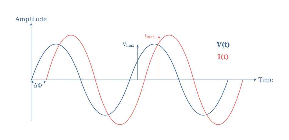
where is the phase angle between voltage and current. A power factor of 1 means all the apparent power is doing useful work. Anything less than 1 means some portion is reactive.
Power Relationships
- In a purely resistive circuit, and . Voltage and current are in phase.
- When reactive elements (inductors or capacitors) are present, because some power is reactive.
- The power triangle captures these relationships geometrically: is the hypotenuse, is the horizontal side, and is the vertical side.
Calculating Apparent Power
Complex Power Using Phasors
The most general way to compute apparent power is with the complex power formula:
where is the voltage phasor and is the complex conjugate of the current phasor. Taking the conjugate of the current (flipping the sign of its angle) is what makes the math correctly separate real and reactive components.
The magnitude of apparent power is simply:
Single-Phase and Three-Phase Systems
For a single-phase system:
For a balanced three-phase system:
where is the line-to-line voltage and is the line current. The factor comes from the geometry of three-phase phasor relationships.

Complex Power in Rectangular and Polar Form
You can express complex power in two equivalent ways:
- Rectangular form:
- Polar form:
The angle is the phase difference between voltage and current. From the rectangular form, you can read off real power (the real part) and reactive power (the imaginary part) directly. This is one of the most useful results in AC power analysis.
Real Power Consumption
Calculation Methods
Real power is the component of apparent power aligned with the voltage-current phase relationship:
For single-phase systems:
For balanced three-phase systems:
Power Factor Characteristics
The type of load determines the power factor behavior:
- Resistive loads have (unity). Voltage and current are in phase, so all apparent power is real power.
- Inductive loads (motors, transformers) have a lagging power factor (). Current lags behind voltage.
- Capacitive loads have a leading power factor (). Current leads voltage.
Power factor correction is the practice of adding parallel capacitors to an inductive load. The capacitor supplies reactive power locally, reducing the reactive power the source must deliver. This brings the power factor closer to unity, which reduces current draw and transmission losses for the same real power delivered.
Power Triangle Relationships
Geometric Analysis
The power triangle is a right triangle where:
- (apparent power) is the hypotenuse
- (real power) is the adjacent side (horizontal)
- (reactive power) is the opposite side (vertical)
The Pythagorean theorem ties them together:
The angle at the base of the triangle is the same phase angle between voltage and current, and equals the power factor.
Trigonometric Relationships
From the triangle, you can derive any quantity if you know two others:
As the power factor approaches unity (), , which means and . The circuit behaves more and more like a purely resistive load.
Practical Use of the Power Triangle
The power triangle is your go-to tool for:
- Converting between , , and when you only know two of the three
- Figuring out how much capacitive VAR you need to add for power factor correction
- Quickly checking whether a circuit is inductive (positive ) or capacitive (negative )
Implications of Reactive Power
System Performance
Reactive power doesn't do useful work, but it's not harmless. It still causes current to flow through conductors, which means:
- Increased transmission losses in wires and cables
- Reduced system capacity, since generators and transformers must be rated for apparent power, not just real power
- Voltage regulation problems in distribution networks, especially at the end of long feeders
Utility companies often penalize industrial customers with low power factors (typically below 0.9) because the extra current needed to supply reactive power costs the utility without generating billable energy.
Power System Management
Several devices are used to manage reactive power on a larger scale:
- Synchronous condensers (over-excited synchronous motors that generate leading reactive power)
- Static VAR compensators (SVCs) that adjust reactive power output dynamically
- Capacitor banks switched in and out as load conditions change
Excessive reactive power causes overheating in generators, transformers, and transmission lines, which can shorten equipment lifespan and reduce efficiency.
Relevance to Modern Power Systems
Reactive power management is critical for integrating renewable energy sources like wind farms and solar arrays. These sources use power electronic inverters that must be programmed to supply or absorb reactive power to maintain grid voltage stability and comply with grid codes. Smart grid technologies use real-time monitoring to adjust reactive power flow continuously, keeping the system balanced as generation and load conditions change.