Step and natural responses are crucial concepts in understanding first-order circuits. They describe how circuits behave when subjected to sudden input changes or when relying on stored energy. These responses help engineers analyze and design circuits for various applications, from power supplies to sensor systems.

RC and RL circuits exhibit exponential behavior in their step and natural responses. The , τ, determines the rate of change in these responses. Understanding these concepts is essential for predicting circuit behavior, designing control systems, and optimizing energy dissipation in electrical systems.

Step Response vs Natural Response

Defining Step and Natural Responses

Top images from around the web for Defining Step and Natural Responses
  • describes circuit behavior when subjected to sudden input change (voltage or current step function)
  • characterizes circuit behavior with no external excitation, relying on stored energy in components
  • First-order circuits contain one energy storage element ( or ) exhibiting exponential responses
  • Step response combines natural response and forced response for complete solution
  • Time constant (τ) determines rate of change in circuit behavior for both responses
  • Step response typically reaches non-zero final value, natural response decays to zero in stable circuits
  • Initial circuit conditions significantly influence both responses

Key Differences and Applications

  • Step response involves external input, natural response relies on internal energy
  • Step response used to analyze circuit behavior under sudden changes (switching circuits, power supplies)
  • Natural response crucial for understanding transient behavior and energy dissipation (oscillators, timing circuits)
  • Step response calculations often require both forced and natural response components
  • Natural response calculations focus solely on energy decay within the circuit
  • Time constants differ between responses (step response reaches 63.2% of final value after one τ, natural response decays by 63.2%)
  • Engineers use step response to design control systems, natural response to analyze circuit stability

Step Response of RC and RL Circuits

RC Circuit Step Response

  • RC circuit step response characterized by exponential charging or discharging of capacitor
  • General form of RC step response: v(t)=A+Bet/τv(t) = A + Be^{-t/τ} (A = final value, B = transient component)
  • Time constant for RC circuit: τ=RCτ = RC
  • Capacitor voltage reaches 63.2% of final value after one time constant, 98.2% after five time constants
  • Charging RC circuit example: 5V step input, R = 10kΩ, C = 100µF, τ=1msτ = 1ms, v(t)=5(1et/0.001)v(t) = 5(1 - e^{-t/0.001}) V
  • Discharging RC circuit example: Initially charged 5V capacitor, R = 20kΩ, C = 47µF, τ=0.94msτ = 0.94ms, v(t)=5et/0.00094v(t) = 5e^{-t/0.00094} V

RL Circuit Step Response

  • RL circuit step response involves exponential increase or decrease in inductor current
  • General form of RL step response: i(t)=A+Bet/τi(t) = A + Be^{-t/τ} (A = final value, B = transient component)
  • Time constant for RL circuit: τ=L/Rτ = L/R
  • Inductor current reaches 63.2% of final value after one time constant, 98.2% after five time constants
  • RL circuit with increasing current example: 2A step input, R = 5Ω, L = 10mH, τ=2msτ = 2ms, i(t)=2(1et/0.002)i(t) = 2(1 - e^{-t/0.002}) A
  • RL circuit with decreasing current example: Initially 3A through inductor, R = 8Ω, L = 16mH, τ=2msτ = 2ms, i(t)=3et/0.002i(t) = 3e^{-t/0.002} A

Analyzing Various Input Signals

  • Input signals include voltage steps, current steps, and pulse inputs, each producing different circuit behaviors
  • Voltage step example: 0V to 10V step in RC circuit triggers capacitor charging
  • Current step example: 0A to 5A step in RL circuit causes inductor current to rise exponentially
  • Pulse input example: Square wave applied to RC circuit results in periodic charging and discharging
  • Superposition principle applies for analyzing complex input signals (multiple steps or pulses)
  • Ramp input example: Linearly increasing voltage applied to RL circuit produces exponential current response with linear component
  • Sinusoidal input example: AC voltage applied to RC circuit results in phase-shifted sinusoidal output

Natural Response of RC and RL Circuits

RC Circuit Natural Response

  • RC natural response governed by homogeneous differential equation without forcing function
  • Involves capacitor discharge through , following exponential decay
  • General form of RC natural response: v(t)=Ket/τv(t) = Ke^{-t/τ} (K determined by initial conditions)
  • Energy stored in capacitor (as voltage) drives natural response, dissipating through resistor
  • Example: 10V initially charged capacitor, R = 100kΩ, C = 10µF, τ=1sτ = 1s, v(t)=10etv(t) = 10e^{-t} V
  • Polarity of initial capacitor voltage determines direction of natural response
  • RC natural response applications include timing circuits (555 timer) and analog-to-digital converters

RL Circuit Natural Response

  • RL natural response characterized by current decay in inductor, following exponential pattern
  • General form of RL natural response: i(t)=Ket/τi(t) = Ke^{-t/τ} (K determined by initial conditions)
  • Energy stored in inductor (as current) drives natural response, dissipating through resistor
  • Example: 2A initial current through inductor, R = 50Ω, L = 100mH, τ=2msτ = 2ms, i(t)=2et/0.002i(t) = 2e^{-t/0.002} A
  • Initial direction of inductor current determines direction of natural response
  • RL natural response applications include inductive kick in relay circuits and current decay in electromagnets

Role in Circuit Behavior

  • Natural response crucial for determining transient behavior after input or configuration changes
  • Contributes to overall step response by defining initial behavior immediately following input change
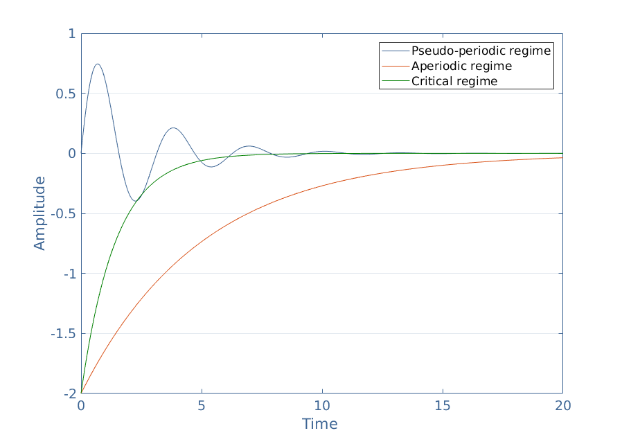
  • Influences circuit stability and oscillation characteristics (, , responses)
  • Determines energy dissipation rate in reactive components (capacitors and inductors)
  • Affects settling time in switching circuits and power supplies
  • Plays role in of filters and resonant circuits
  • Impacts signal integrity in high-speed digital circuits (ringing and reflections)

Applying Step and Natural Responses

Problem-Solving Approach

  • Identify circuit type (RC or RL) and calculate appropriate time constant (τ=RCτ = RC or τ=L/Rτ = L/R)
  • Establish initial conditions by analyzing circuit state before input signal or switch action
  • For step response, determine final steady-state voltages and currents
  • Combine natural and forced responses for complete step response solution
  • Use exponential functions and time constant to calculate voltages or currents at specific times
  • Apply KVL (Kirchhoff's Voltage Law) and KCL (Kirchhoff's Current Law) for complex circuit analysis
  • Analyze energy transfer between capacitors and inductors during transient period

Practical Applications and Examples

  • Power supply design: Analyze turn-on transients in voltage regulators (step response of RC filter)
  • Motor control: Model inrush current in DC motors (step response of RL circuit)
  • Sensor circuits: Determine response time of capacitive sensors (RC natural response)
  • Signal conditioning: Design low-pass filters for noise reduction (RC step response)
  • Timing circuits: Create monostable multivibrators using RC natural response
  • Magnetic field decay: Analyze eddy current effects in transformers (RL natural response)
  • Transmission lines: Model signal propagation and reflections (distributed RC and RL effects)

Key Terms to Review (19)

Bode Plot: A Bode plot is a graphical representation of a linear, time-invariant system's frequency response, typically plotted with magnitude (in decibels) and phase (in degrees) against frequency (on a logarithmic scale). This tool allows for quick insights into how a system behaves in response to sinusoidal inputs, providing valuable information on stability and performance characteristics like gain and phase margins.
Capacitor: A capacitor is an electronic component that stores and releases electrical energy in a circuit, characterized by its ability to hold a charge when voltage is applied. This fundamental property connects capacitors to various circuit elements and configurations, impacting voltage, current, and power dynamics within electrical systems.
Critically damped: Critically damped refers to a specific condition in a second-order linear system where the system returns to equilibrium in the shortest time without oscillating. This state is crucial for system stability and response characteristics, as it ensures that the system does not overshoot or oscillate around the equilibrium point, leading to a rapid stabilization.
Differential Equations: Differential equations are mathematical equations that relate a function to its derivatives, capturing the relationship between a quantity and the rate of change of that quantity. They play a critical role in analyzing dynamic systems and can describe phenomena such as electrical circuits' behavior over time, particularly during transient states or when responding to changes like step inputs.
Frequency response: Frequency response is the measure of a system's output spectrum in response to an input signal of varying frequency, typically expressed as a function of frequency. It describes how a circuit or system reacts to different frequencies of input signals, helping to analyze stability and performance. Understanding frequency response is essential for evaluating the behavior of both RLC circuits and various damping responses when subjected to sinusoidal excitations.
Inductor: An inductor is a passive electrical component that stores energy in a magnetic field when electric current flows through it. It plays a vital role in circuit designs, particularly in filtering, energy storage, and tuning applications, by influencing the flow of current and voltage in various configurations.
Laplace Transform: The Laplace Transform is a powerful mathematical technique used to transform time-domain functions into the frequency domain, making it easier to analyze linear time-invariant systems. It allows engineers and scientists to simplify complex differential equations, especially in the context of circuit analysis and control systems, by converting them into algebraic equations. This transformation is essential for studying system behaviors like transient and steady-state responses to various inputs.
Natural Response: Natural response refers to the behavior of a system when it is allowed to evolve freely without external input, typically following an initial disturbance. This response is characterized by the system returning to its equilibrium state over time, showcasing its inherent properties such as resistance and capacitance in electrical circuits. The natural response is crucial for understanding how systems behave in the absence of external forcing functions and is essential for analyzing circuit dynamics.
Overdamped: Overdamped refers to a type of system response characterized by the absence of oscillations and a slower return to equilibrium after a disturbance. This occurs when the damping ratio is greater than one, meaning that the system experiences excessive resistance to motion, leading to a gradual decay in amplitude over time. In practical terms, an overdamped system takes longer to stabilize compared to critically damped or underdamped systems.
Resistor: A resistor is a passive electrical component that resists the flow of electric current, creating a voltage drop across its terminals. Resistors play a critical role in controlling current and voltage levels within circuits, making them fundamental to various applications in electrical engineering.
Rise time: Rise time is the duration it takes for a signal to change from a defined low value to a defined high value, typically measured from 10% to 90% of its maximum amplitude. This concept is crucial for understanding how quickly a system can respond to changes, especially in the context of step and natural responses, where the speed of a signal's transition can significantly affect overall system performance.
State-space analysis: State-space analysis is a mathematical approach used to model and analyze dynamic systems by representing them in terms of state variables and equations. This method provides a comprehensive framework for understanding the behavior of systems over time, especially when subjected to different inputs or initial conditions. By leveraging state-space representations, one can derive important characteristics such as natural and step responses, which describe how systems respond to various stimuli.
Steady-state response: Steady-state response refers to the behavior of a circuit after all transient effects have dissipated, and the circuit is in equilibrium. In this state, the circuit responds predictably to constant inputs, such as DC voltage or constant sinusoidal sources, allowing for the analysis of long-term performance without the complications introduced by initial conditions or transient responses.
Step response: The step response of a system describes how the output behaves in reaction to a sudden change in input, specifically a step input. This concept is crucial for understanding how systems respond to changes over time, revealing important characteristics such as stability, oscillations, and settling time. By analyzing the step response, we can gain insights into the system’s performance and transient behavior, making it an essential aspect of dynamic system analysis.
Superposition Theorem: The superposition theorem states that in a linear circuit with multiple independent sources, the total response (voltage or current) at any point in the circuit can be determined by summing the responses produced by each independent source acting alone, with all other independent sources turned off. This theorem is crucial for simplifying the analysis of complex circuits by breaking them down into more manageable parts.
Time constant: The time constant is a measure of the time it takes for a circuit to charge or discharge to approximately 63.2% of its maximum voltage or current. This concept is fundamental in analyzing how quickly a system responds to changes, impacting the behavior of both capacitors and inductors in electrical circuits.
Transient Response: Transient response refers to the behavior of a circuit when it is subjected to a sudden change, such as a voltage or current step input. This response is characterized by a temporary state that occurs before the system settles into a steady-state condition. The transient response is influenced by the components of the circuit, such as capacitors and inductors, and plays a crucial role in understanding the dynamics of RLC circuits and their natural and step responses.
Transmission line theory: Transmission line theory is a framework used to analyze the behavior of electrical signals as they travel through transmission lines, which are specialized conductors designed to carry alternating current (AC) or high-frequency signals. This theory focuses on the relationships between voltage, current, and impedance along the line, taking into account the effects of line length, capacitance, inductance, and resistance. Understanding this theory is essential for predicting how signals will propagate, reflect, and attenuate in various circuit configurations.
Underdamped: Underdamped refers to a condition in dynamic systems where the response to a disturbance oscillates while gradually decreasing in amplitude over time. This behavior is characterized by a system that has insufficient damping, leading to oscillations before it eventually settles at a steady state. Underdamped systems are significant as they illustrate how energy is dissipated through oscillatory motion, making them essential in understanding transient responses and stability.
© 2024 Fiveable Inc. All rights reserved.
AP® and SAT® are trademarks registered by the College Board, which is not affiliated with, and does not endorse this website.