AP exam review verified for 2027

AP Physics 2 Unit 11 Review: Electric Circuits

Review AP Physics 2 Unit 11 to build a complete picture of how electric circuits work, from current and resistance through Kirchhoff's rules and RC transients. This unit carries 15-18% of the exam and rewards students who can reason through circuit behavior qualitatively and quantitatively.

Use the topic guides, practice questions, FRQ practice, and AP score calculator available for this unit to focus your review.

What is AP Physics 2 unit 11?

Electric circuits build directly on the electric potential concepts from Unit 10. In Unit 11, potential difference drives current through resistors and capacitors arranged in series, parallel, or mixed networks. The unit progresses from defining current and resistance to analyzing multi-loop circuits and finally to the transient charging and discharging behavior of RC circuits.

Unit 11 is about how charge flows through circuits, how resistors and capacitors affect that flow, and how energy is transferred. You use Ohm's law, power equations, Kirchhoff's rules, and the RC time constant to analyze and predict circuit behavior.

Current, Resistance, and Ohm's Law

Current I = Δq/Δt measures charge flow rate in amperes. Resistance depends on material resistivity and geometry via R = ρℓ/A. Ohm's law I = ΔV/R links these quantities for ohmic materials, where an I-V graph is a straight line with slope 1/R.

Series, Parallel, and Power

Resistors in series share the same current; resistors in parallel share the same voltage. Equivalent resistance lets you simplify networks. Power dissipated by any element is P = IΔV, also written as P = I²R or P = (ΔV)²/R, and bulb brightness scales directly with power.

Kirchhoff's Rules and RC Circuits

The loop rule (ΣΔV = 0) applies conservation of energy around any closed loop. The junction rule (ΣI_in = ΣI_out) applies conservation of charge at any node. In RC circuits, the time constant τ = R_eq C_eq sets how quickly a capacitor charges to 63% or discharges to 37% of its value.

Conservation laws drive every circuit analysis

Every major tool in Unit 11 is an application of a conservation law. Kirchhoff's loop rule is conservation of energy: a charge returning to its starting point has zero net change in potential. Kirchhoff's junction rule is conservation of charge: current cannot accumulate at a node. Even the RC time constant reflects how charge redistributes over time while total charge is conserved. Recognizing which conservation law applies is the core reasoning skill the exam tests.

AP Physics 2 unit 11 topics

11.1

Electric Current

Current I = Δq/Δt measures charge flow rate. Conventional current direction is defined by positive charge motion, opposite to electron flow in metals. emf drives charge through a circuit.

open guide
11.2

Simple Circuits

Circuits are closed loops of elements including batteries, resistors, bulbs, and meters. Closed circuits allow current; open circuits do not. Schematics use standard symbols and element arrangement determines behavior.

open guide
11.3

Resistance, Resistivity, and Ohm's Law

Resistance R = ρℓ/A depends on material and geometry. Ohm's law I = ΔV/R applies to ohmic materials with constant resistance. An I-V graph for an ohmic resistor is a straight line with slope 1/R.

open guide
11.4

Electric Power

Power P = IΔV = I²R = (ΔV)²/R gives the rate of energy transfer. Bulb brightness increases with power, allowing qualitative ranking of bulbs in series or parallel circuits.

open guide
11.5

Compound DC Circuits

Series resistors add directly; parallel resistors combine by reciprocal sums. Real batteries have internal resistance, reducing terminal voltage below emf. Mixed networks are simplified by finding equivalent resistance step by step.

open guide
11.6

Kirchhoff's Loop Rule

ΣΔV = 0 around any closed loop, reflecting conservation of energy. Track potential rises across batteries and drops across resistors to write loop equations and solve for unknown quantities.

open guide
11.7

Kirchhoff's Junction Rule

ΣI_in = ΣI_out at every junction, reflecting conservation of charge. Apply at nodes where current branches split or recombine to write current equations for multi-loop circuits.

open guide
11.8

RC Circuits

Capacitors combine in series (reciprocal sum) or parallel (direct sum). The time constant τ = R_eq C_eq sets the charging and discharging rate. At t = 0 an uncharged capacitor acts as a wire; at steady state it acts as an open circuit.

open guide
practice snapshot

Hardest AP Physics 2 unit 11 topics

This snapshot uses Fiveable practice activity to show where students tend to miss questions and which review moves are worth prioritizing first.

55%average MCQ accuracy

Across 1.6k multiple-choice practice attempts for this unit.

1.6kMCQ attempts

Practice activity included in this snapshot.

90%average FRQ score

Across 1 scored free-response attempts for this unit.

Hardest topics in unit 11

MCQ miss rate
11.3

Review Resistance, Resistivity, and Ohm's Law with attention to how the concept appears in AP-style source and evidence questions.

49%199 tries
11.1

Review Electric Current with attention to how the concept appears in AP-style source and evidence questions.

48%267 tries
11.7

Review Kirchhoff's Junction Rule with attention to how the concept appears in AP-style source and evidence questions.

43%182 tries
11.4

Review Electric Power with attention to how the concept appears in AP-style source and evidence questions.

39%252 tries

Unit 11 review notes

11.1

Electric Current

Current is the rate at which charge passes through a cross-sectional area of a wire, defined as I = Δq/Δt and measured in amperes. Charge moves in response to an electric potential difference, also called emf (ε). Conventional current direction is defined as the direction positive charge would move, which is opposite to the actual motion of electrons in a metal. Current is not a vector, but it does have a direction that is independent of any coordinate system.

  • I = Δq/Δt: Current equals charge transferred divided by time elapsed; units are amperes (A = C/s).
  • Conventional current: Defined as the direction positive charge would flow; in metals, electrons move opposite to this direction.
  • emf (ε): The energy per unit charge supplied by a source like a battery that drives current around a circuit.
  • Zero current: If net current is zero in a wire, the net motion of charge carriers is zero, but individual electrons still move randomly at thermal speeds.
If a wire carries 2 A for 5 s, how much charge passed through a cross section? (Answer: 10 C using I = Δq/Δt.)
11.2

Simple Circuits and Schematics

A circuit is one or more electrical loops containing elements such as batteries, resistors, bulbs, capacitors, switches, ammeters, and voltmeters. Charge can only flow in a closed loop. Circuit schematics use standard symbols for each element, and the physical arrangement of elements determines circuit behavior. Ammeters are placed in series; voltmeters are placed in parallel with the element being measured.

  • Closed circuit: A complete loop through which charge can flow continuously.
  • Open circuit: A broken loop where charge cannot flow; current is zero throughout.
  • Short circuit: A path where charge flows with no change in potential difference, bypassing other elements.
  • Ammeter placement: Connected in series so the same current flows through it; ideal ammeter has zero resistance.
  • Voltmeter placement: Connected in parallel across an element; ideal voltmeter has infinite resistance.
A switch is opened in a single-loop circuit. What happens to the current everywhere in the loop? (Answer: Current drops to zero because the loop is no longer closed.)
Circuit typeCurrent flows?Potential difference across elements?
Closed circuitYesYes, distributed across elements
Open circuitNoFull source voltage appears across the gap
Short circuitYes, very largeZero across the shorted element
11.3

Resistance, Resistivity, and Ohm's Law

Resistance measures how strongly an object opposes charge flow. For a uniform conductor, R = ρℓ/A, where ρ is the material's resistivity, ℓ is length, and A is cross-sectional area. Resistivity is a material property that typically increases with temperature for conductors. Ohm's law, I = ΔV/R, applies to ohmic materials, which have constant resistance regardless of current. On an I-V graph, an ohmic resistor produces a straight line; the slope equals 1/R. Resistors also convert electrical energy to thermal energy (Joule heating), which can raise the temperature of the resistor and its surroundings.

  • R = ρℓ/A: Resistance increases with length and resistivity, and decreases with larger cross-sectional area.
  • Ohmic material: A material with constant resistivity; its I-V graph is a straight line through the origin.
  • Resistivity temperature dependence: For metallic conductors, resistivity increases as temperature rises.
  • I-V graph slope: The slope of an I vs. ΔV graph equals 1/R; a steeper slope means lower resistance.
  • Joule heating: Thermal energy produced in a resistor when current flows through it, given by P = I²R.
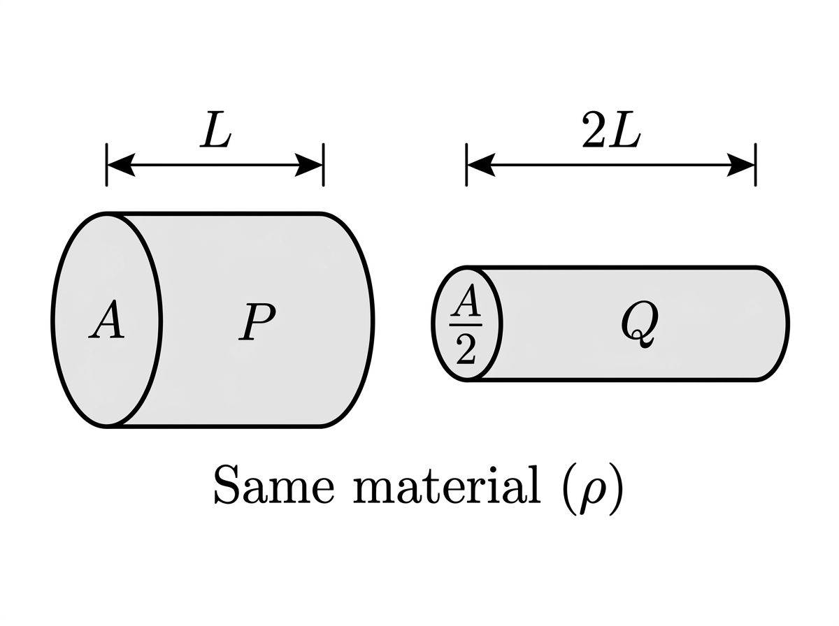
A wire is replaced with one of the same material but twice the length and half the cross-sectional area. By what factor does resistance change? (Answer: R increases by a factor of 4, since both changes multiply resistance.)
11.4

Electric Power

Power is the rate at which energy is transferred or dissipated by a circuit element. The fundamental equation is P = IΔV. Combining with Ohm's law gives two derived forms: P = I²R (useful when you know current and resistance) and P = (ΔV)²/R (useful when you know voltage and resistance). Bulb brightness increases with power, so you can rank bulbs in a circuit by comparing their power values without calculating exact brightness.

  • P = IΔV: Power dissipated or delivered equals current times potential difference across the element.
  • P = I²R: Use this form when current through the element is known.
  • P = (ΔV)²/R: Use this form when voltage across the element is known.
  • Bulb brightness: Brightness is proportional to power; a bulb with higher power dissipation glows brighter.
Two identical bulbs are connected in series to a battery. A third identical bulb is then added in series. Does each bulb get brighter, dimmer, or stay the same? (Answer: Dimmer, because total resistance increases, current decreases, and P = I²R falls for each bulb.)
FormulaBest used whenVariable held constant
P = IΔVBoth I and ΔV are knownNeither
P = I²RCurrent I is knownCurrent same in series
P = (ΔV)²/RVoltage ΔV is knownVoltage same in parallel
11.5

Compound DC Circuits

Resistors in series carry the same current; their equivalent resistance is R_eq = R1 + R2 + ... Resistors in parallel share the same potential difference; their equivalent resistance satisfies 1/R_eq = 1/R1 + 1/R2 + ... Real batteries have internal resistance r, so the terminal voltage is ΔV_terminal = ε - Ir, which is less than the emf when current flows. Simplifying a mixed network means repeatedly combining series and parallel groups until one equivalent resistance remains.

  • Series resistors: Same current through each; R_eq = sum of all individual resistances.
  • Parallel resistors: Same voltage across each; 1/R_eq = sum of reciprocals of individual resistances.
  • Terminal voltage: ΔV_terminal = ε - Ir; the voltage a real battery delivers drops as current increases.
  • Voltage divider: In a series circuit, each resistor's voltage is proportional to its fraction of total resistance.
A 12 V battery with internal resistance 1 Ω drives a 5 Ω external resistor. What is the terminal voltage? (Answer: I = 12/6 = 2 A; terminal voltage = 12 - 2(1) = 10 V.)
PropertySeries connectionParallel connection
CurrentSame through all resistorsSplits among branches
VoltageDivides across resistorsSame across all branches
Equivalent resistanceR_eq = ΣR_i (larger than any single R)1/R_eq = Σ(1/R_i) (smaller than any single R)
11.6

Kirchhoff's Loop Rule

Kirchhoff's loop rule states that the sum of all potential differences around any single closed loop equals zero: ΣΔV = 0. This is a direct consequence of conservation of energy: a charge that travels around a complete loop returns to the same electric potential it started at. When applying the rule, track potential rises (across a battery from - to +) and potential drops (across a resistor in the direction of current) consistently. A graph of electric potential versus position around a loop shows these rises and drops as a visual check.

  • ΣΔV = 0: The algebraic sum of all potential differences around any closed loop is zero.
  • Potential rise: Moving through a battery from negative to positive terminal adds +ε to the loop sum.
  • Potential drop: Moving through a resistor in the direction of current subtracts IR from the loop sum.
  • Energy conservation basis: The loop rule holds because electric potential energy is a state function; a full loop returns to the starting potential.
A loop contains a 9 V battery and two resistors of 2 Ω and 1 Ω in series. Write the loop equation and solve for current. (Answer: 9 - 2I - 1I = 0, so I = 3 A.)
11.7

Kirchhoff's Junction Rule

Kirchhoff's junction rule states that the total current entering any junction equals the total current leaving it: ΣI_in = ΣI_out. This follows from conservation of charge: charge cannot accumulate at a node in a steady-state circuit. The junction rule is the key tool for writing equations at nodes in multi-branch circuits, and it works together with the loop rule to solve for all unknown currents.

  • ΣI_in = ΣI_out: Current entering a junction must equal current leaving it; no charge builds up at a node.
  • Conservation of charge basis: The junction rule holds because charge is conserved; it cannot pile up at an ordinary circuit node.
  • Junction vs. loop rule: Use the junction rule at nodes where current splits or recombines; use the loop rule along closed paths.
At a junction, three branches carry currents of 3 A in, 1 A in, and an unknown current out. What is the unknown current? (Answer: 4 A out, by ΣI_in = ΣI_out.)
RuleConservation lawEquationWhere to apply
Loop ruleConservation of energyΣΔV = 0Around any closed loop
Junction ruleConservation of chargeΣI_in = ΣI_outAt any node where currents split or merge
11.8

RC Circuits and Equivalent Capacitance

Capacitors in series satisfy 1/C_eq = Σ(1/C_i), giving an equivalent capacitance smaller than the smallest individual capacitor. Capacitors in parallel satisfy C_eq = ΣC_i. In an RC circuit, the time constant τ = R_eq C_eq determines how quickly the capacitor charges or discharges. After one time constant, a charging capacitor reaches about 63% of its final charge; a discharging capacitor retains about 37% of its initial charge. Immediately after a switch closes, an uncharged capacitor behaves like a short circuit (wire). After a long time, it behaves like an open circuit and no current flows through its branch.

  • Series capacitors: 1/C_eq = Σ(1/C_i); equivalent capacitance is less than the smallest capacitor in the group.
  • Parallel capacitors: C_eq = ΣC_i; equivalent capacitance is the sum of all individual capacitances.
  • Time constant τ = R_eq C_eq: Sets the timescale for charging or discharging; larger τ means slower response.
  • Transient response: At t = 0, an uncharged capacitor acts as a short circuit; at t → ∞ (steady state), it acts as an open circuit.
  • Steady state: After many time constants, capacitor voltage and circuit currents stop changing; no current flows through the capacitor branch.
An RC circuit has R = 2000 Ω and C = 500 μF. What is τ, and what fraction of final charge has the capacitor reached after one time constant? (Answer: τ = 2000 × 0.0005 = 1 s; the capacitor is at 63% of final charge.)
Capacitor configurationEquivalent capacitance formulaCompared to individual values
Series1/C_eq = Σ(1/C_i)Smaller than the smallest C
ParallelC_eq = ΣC_iLarger than the largest C

Practice AP Physics 2 unit 11 questions

Try stimulus-based AP practice questions and written prompts after you review the notes.

Example stimulus-based MCQs

open all practice
schematic

Stimulus-based practice question

schematic

The circuit shown contains an ideal battery and four identical lightbulbs labeled A, B, C, and D. Bulb A is in series with the battery, while bulbs B, C, and D are connected in a separate parallel combination that is in series with bulb A.

Question

Which of the following correctly predicts the relative brightness of bulb A compared to bulb B when the circuit is operating normally?

Bulb A is brighter than bulb B because more current flows through A than through B.

Bulb B is brighter than bulb A because bulb B has a higher potential difference across it.

Bulbs A and B have equal brightness because they are connected to the same battery.

Bulb B is brighter than bulb A because the parallel combination reduces resistance, increasing current through each parallel branch.

diagram

Stimulus-based practice question

diagram

The figure shows two cylindrical resistors, P and Q, made of the same material. Resistor P has length L and cross-sectional area A. Resistor Q has length 2L and cross-sectional area A/2. A student applies the resistance equation to compare the two resistors.

Question

Which of the following correctly applies R = ρℓ/A to compare the resistance of Resistor Q to the resistance of Resistor P?

R_Q = 4R_P, because doubling the length doubles the resistance and halving the area doubles it again.

R_Q = 2R_P, because only the length doubles while the area remains proportionally the same.

R_Q = R_P, because the volume of both resistors is the same (L·A = 2L·A/2).

R_Q = R_P/2, because the smaller cross-sectional area reduces the total amount of resistive material.

Example FRQs

open all FRQs
FRQ

Battery terminal voltage and internal resistance determination

3. In Experiment 1, a student is given a battery of unknown emf and unknown internal resistance. The student is asked to predict how the battery’s terminal potential difference changes as the current supplied by the battery changes when different external resistors are connected.

A.

Describe a procedure for collecting data that would allow the student to determine the battery’s emf and internal resistance. In your description, include the measurements to be made. Include any steps necessary to reduce experimental uncertainty.

B.

Describe how the collected data could be analyzed to determine the battery’s emf and internal resistance. Include references to appropriate equations and to relationships between measured and known quantities.

Figure 1. Circuit used to measure the battery terminal potential difference and current for different external resistors.

A clean black-and-white physics circuit diagram occupying the full frame, drawn as a single rectangular loop with right-angle corners.

Overall layout (clockwise from top left corner):
- Top wire: a straight horizontal line across the upper third of the figure.
- Right wire: a straight vertical line down the right side.
- Bottom wire: a straight horizontal line across the lower third.
- Left wire: a straight vertical line up the left side, closing the loop.

Components placed on the loop (with exact relative positions):
1) Battery with internal resistance (left side, centered vertically):
   - On the left vertical wire, replace a short segment at the vertical midpoint with a battery symbol (one long plate and one short plate) in series with a small resistor symbol.
   - The battery plates are drawn immediately above the small resistor symbol so the two symbols appear as a single combined element on the left branch.
   - Label placed to the left of this combined element: "Battery" on the first line, and directly below it "emf = ε (unknown)" and "internal resistance = r (unknown)".
   - Mark the upper terminal of the battery as the positive terminal by placing a visible "+" sign next to the upper plate; mark the lower terminal with a visible "−" sign next to the lower plate.

2) Switch (top wire, left of center):
   - Insert a standard open switch symbol in the top wire in the left half of the loop, closer to the battery than to the right side.
   - The switch is drawn open (a gap with the lever not touching).
   - Label "Switch S" placed directly above the switch symbol.

3) Ammeter (top wire, right of center):
   - Insert a circular ammeter symbol labeled "A" in the top wire in the right half of the loop, between the switch and the top-right corner.
   - Label "Ammeter" placed directly above the circle.
   - Near the ammeter, place a small text label on the wire indicating the measured current: "I".

4) External resistor (right side, centered vertically):
   - On the right vertical wire, replace a segment at the vertical midpoint with a zigzag resistor symbol.
   - Label to the right of the resistor: "External resistor R".
   - Add a note directly beneath that label: "Replace R with different known resistors" (this is visible text).

Voltmeter connection (across the battery terminals):
- Draw a voltmeter as a circle labeled "V" located just outside the left side of the loop, positioned horizontally level with the battery.
- Two thin leads connect from the voltmeter to the battery terminals:
  - The upper voltmeter lead connects to the wire node at the battery’s upper terminal (the same node marked with "+").
  - The lower voltmeter lead connects to the wire node at the battery’s lower terminal (the same node marked with "−").
- Place a text label next to the voltmeter circle: "Voltmeter".
- Place an additional label near the voltmeter leads (centered between them): "V_terminal" (visible exactly as text with the underscore).

Direction indication:
- On the top wire between the switch and the ammeter, draw a single right-pointing arrow on the wire labeled "I" to indicate conventional current direction from left to right along the top branch.

Style constraints:
- No numerical values are printed on any component in this figure.
- All labels are clearly separated from symbols, with short leader lines only where needed (for the external resistor and the battery).

Figure 2. Graph of battery terminal potential difference versus current for determining emf and internal resistance.

A full-page Cartesian graph grid intended for student plotting, with a rectangular plotting area and light gray gridlines.

Axes and scale (all numbers shown as tick labels):
- Horizontal axis: labeled "Current, I (A)" centered below the axis.
  - Range: from 0.00 at the origin to 0.30 at the far right end.
  - Major tick marks every 0.05 A, labeled exactly: 0.00, 0.05, 0.10, 0.15, 0.20, 0.25, 0.30.
  - Minor gridlines every 0.01 A (unlabeled), producing five minor divisions between each adjacent major tick.
- Vertical axis: labeled "Terminal potential difference, V_terminal (V)" rotated vertically along the left side.
  - Range: from 1.60 at the bottom edge to 2.00 at the top edge.
  - Major tick marks every 0.05 V, labeled exactly: 1.60, 1.65, 1.70, 1.75, 1.80, 1.85, 1.90, 1.95, 2.00.
  - Minor gridlines every 0.01 V (unlabeled), producing five minor divisions between each adjacent major tick.
- Origin labeling requirement: At the intersection of the axes, the x-axis tick at the origin is labeled "0.00" and the y-axis tick at the bottom of the y-axis is labeled "1.60". (The figure does not show a y=0 scale because the y-axis starts at 1.60 V.)
- Arrowheads: a single arrowhead on the positive (right) end of the horizontal axis, and a single arrowhead on the positive (top) end of the vertical axis.

Plotted data points (exactly five solid markers, no coordinate text printed):
- Plot five filled circular points corresponding to the Table 1 measurements, positioned exactly at the intersections of the appropriate vertical and horizontal gridlines:
  1) A point located directly above the x-axis tick labeled 0.30 and exactly level with the y-axis tick labeled 1.70.
  2) A point located directly above the x-axis tick labeled 0.20 and exactly level with the y-axis tick labeled 1.80.
  3) A point located directly above the x-axis tick labeled 0.15 and exactly level with the y-axis tick labeled 1.85.
  4) A point located directly above the x-axis tick labeled 0.10 and exactly level with the y-axis tick labeled 1.90.
  5) A point located directly above the x-axis tick labeled 0.05 and exactly level with the y-axis tick labeled 1.95.

Best-fit line (single straight line, solid, medium thickness):
- Draw one straight best-fit line through the cluster of points with a negative slope (line decreases from left to right).
- The line passes exactly through the two extreme data points: the highest-voltage/lowest-current point (at I=0.05 A and V_terminal=1.95 V) and the lowest-voltage/highest-current point (at I=0.30 A and V_terminal=1.70 V).
- Extend the line slightly beyond the leftmost and rightmost plotted points, but keep it entirely within the graph box.

Curve/line behavior statement (to eliminate ambiguity):
- There is only one plotted relationship and it is strictly linear: a single straight line with constant negative slope; no curves, no piecewise segments, no discontinuities, and no additional lines.

No extra text:
- No title at the top.
- No legend.
- No printing of ordered pairs near the points.

External resistance R (Ω)

Current I (A)

Battery terminal potential difference V_terminal (V)

4.0

0.30

1.70

6.0

0.20

1.80

8.0

0.15

1.85

12.0

0.10

1.90

24.0

0.05

1.95

C.

In Experiment 2, the student uses the setup in Figure 1 with five different external resistors. For each trial, the student records the current I in the circuit and the battery terminal potential difference V_terminal. The data are shown in Table 1.

i.

Indicate two quantities, either measured quantities from Table 1 or additional calculated quantities, that could be graphed to produce a straight line that could be used to determine the battery’s emf and internal resistance.

Vertical axis: Horizontal axis:

ii.

On Figure 2, create a graph of the quantities indicated in part C(i) that can be used to determine the battery’s emf and internal resistance.

Use Table 2 to record the data points or calculated quantities that you will plot.

Clearly label the axes, including units as appropriate.

Plot the points you recorded in Table 2.

iii.

Draw a best-fit line for the data graphed in part C(ii).

D.

Using the best-fit line in part D and appropriate circuit relationships, calculate the power dissipated in the external resistor RR (i) immediately after the switch is closed and (ii) after a long time has passed. Express each answer in watts. The student analyzes the graph from Experiment 2 and finds that the best-fit line for VterminalV_{\text{terminal}} as a function of II is

Vterminal=(2.00 V)(1.00 Ω)IV_{\text{terminal}} = (2.00\ \text{V}) - (1.00\ \Omega)I

The student then connects an external resistor R=6.0 ΩR = 6.0\ \Omega in series with the battery. The student also connects a capacitor of capacitance C=200 μFC = 200\ \mu\text{F} in parallel with the external resistor. Immediately after the switch is closed, the capacitor is uncharged. After a long time, the capacitor is fully charged.

FRQ

Battery, capacitors, and resistive charging

4. A circuit contains a battery of emf E=12.0 V\mathcal{E} = 12.0\ \text{V} with internal resistance r=1.0 Ωr = 1.0\ \Omega, a resistor R=5.0 ΩR = 5.0\ \Omega, and two capacitors C1=6.0 μFC_1 = 6.0\ \mu\text{F} and C2=3.0 μFC_2 = 3.0\ \mu\text{F}, as shown in Figure 1. The two capacitors are connected in parallel with each other, and that parallel combination is connected in series with the resistor RR and the battery. A switch SS is initially open, so no current flows and both capacitors are uncharged. At time t=0t=0 the switch is closed and the circuit begins charging. The circuit is allowed to reach steady state.

Figure 1. Series circuit containing a 12.0 V battery with internal resistance 1.0 Ω, a switch S, a 5.0 Ω resistor, and a parallel combination of capacitors C1 = 6.0 µF and C2 = 3.0 µF.

Draw a clean, rectangular single-loop circuit diagram with a clearly defined top wire (outgoing path) and bottom wire (return path). Use standard circuit symbols in black lines on a white background. All labels and numerical values listed below must appear exactly as text next to the correct component.

Overall layout (rectangular loop):
- The circuit is a wide horizontal rectangle occupying most of the image width.
- The top horizontal wire runs left-to-right across the upper half of the diagram.
- The bottom horizontal wire runs right-to-left across the lower half of the diagram.
- A vertical wire on the left side connects the bottom wire up to the top wire (completing the loop on the left).
- A vertical wire on the right side is not a single uninterrupted segment; instead, the right side contains a parallel-branch section (two branches) that reconnects at the bottom wire.

Left side (battery and internal resistance on the left vertical segment):
- On the left vertical segment, place the battery symbol centered vertically: two parallel plates, the longer plate on top and the shorter plate below (standard battery orientation), inserted into the left vertical wire.
- Immediately adjacent to the battery symbol (still on the left side of the loop), show the internal resistance as a standard resistor symbol in series with the battery, on the same left vertical segment. The internal resistor must be drawn as a zigzag (or rectangular resistor symbol) placed directly above the battery or directly below it, but clearly on the left side branch so it is in series with the entire loop.
- Label the battery with the text: "emf E = 12.0 V" placed next to the battery symbol.
- Label the internal resistor with the text: "r = 1.0 Ω" placed next to the internal resistance symbol.

Top wire components (switch and resistor in series, left to right):
- Along the top horizontal wire, moving from left to right starting just after the left vertical segment, place the switch symbol first.
  - The switch is drawn as a break in the top wire with a lever. Depict the switch in the CLOSED position (contacts touching) to represent the circuit after t = 0.
  - Label it "S" directly above the switch symbol.
- Continue along the same top wire to the right and place the external resistor next.
  - Draw a standard resistor symbol on the top wire, clearly in series after the switch.
  - Label it "R = 5.0 Ω" directly above or below the resistor symbol.

Right side (explicit parallel capacitor network):
- Immediately after the resistor R on the top wire, place a junction node where the single top wire splits into two separate branches.
  - Represent the junction as a filled circular node (dot) where three conductors meet: the incoming top wire from R and two outgoing branch wires.
- From this top junction, draw two distinct branches that run to the right side and then downward to a second junction that reconnects to the bottom wire:
  - Upper branch (for C1):
    - The upper branch leaves the top junction and runs horizontally a short distance, then contains a capacitor symbol oriented vertically (two parallel plates with a gap), so the branch wire goes into the top plate and exits from the bottom plate.
    - After the capacitor, the branch wire continues down to the lower rejoin junction.
    - Label this capacitor clearly as "C1 = 6.0 µF" placed next to the capacitor symbol on the upper branch.
  - Lower branch (for C2):
    - The lower branch leaves the same top junction and runs downward slightly (so it is clearly below the upper branch), then runs horizontally a short distance, then contains a capacitor symbol oriented vertically (same style), and then continues to the same lower rejoin junction.
    - Label this capacitor clearly as "C2 = 3.0 µF" placed next to the capacitor symbol on the lower branch.
- The two branches must reconnect at a single lower junction node (filled dot). This lower junction sits on the right side of the diagram and connects directly into the bottom horizontal return wire.

Bottom return wire:
- Draw the bottom horizontal wire as a continuous line from the right-side lower junction node back to the left vertical segment, completing the rectangle.
- Do not place any components on the bottom wire.

Text and clarity requirements:
- Ensure the parallel nature is visually unambiguous: both capacitors share the same two nodes (the top split junction and the bottom rejoin junction).
- Ensure the series nature is visually unambiguous: battery + internal resistance r + switch S + resistor R + (parallel capacitors) are all in one loop, with the parallel section only occurring at the capacitor network.
- All component labels must be printed exactly as: "emf E = 12.0 V", "r = 1.0 Ω", "S", "R = 5.0 Ω", "C1 = 6.0 µF", and "C2 = 3.0 µF".
- No additional components, arrows, or extraneous annotations are included.
A.

A student claims that immediately after the switch is closed at t=0+t=0^+, the current in the circuit is determined only by the resistors RR and rr because the uncharged capacitors initially behave like a wire, and that at very long times the current becomes zero because charges stop moving through the circuit.

Indicate whether the student's claim is correct or incorrect. Without manipulating equations, justify your answer by describing (i) the movement of electric charges in the circuit at t=0+t=0^+ and as tt \to \infty and (ii) how the potential difference across the capacitor combination changes during the charging process.

B.

Derive an expression for the initial current I0I_0 in the circuit at t=0+t=0^+ and an expression for the steady-state potential difference VC,V_{C,\infty} across the parallel capacitor combination as tt \to \infty. Express your answers in terms of E\mathcal{E}, RR, and rr only. Begin your derivation by writing Kirchhoff's loop rule for the circuit at the appropriate time.

C.

Indicate whether your expressions from part B are or are not consistent with your answer from part A. Briefly justify your answer by referencing how the expressions depend on RR and rr and what happens to the current and potential differences at t=0+t=0^+ and as tt \to \infty.

FRQ

Capacitor charging in multi-resistor circuit

2. A student builds the circuit shown in Figure 1 using an ideal battery, resistors, and capacitors. At time t=0t=0 the switch SS is closed. Before the switch is closed, both capacitors are uncharged. The battery has emf E=12.0 V\mathcal{E}=12.0\ \text{V} and negligible internal resistance. Resistor R1=6.0 ΩR_1=6.0\ \Omega and resistor R2=3.0 ΩR_2=3.0\ \Omega. Capacitor C1=4.0 μFC_1=4.0\ \mu\text{F} and capacitor C2=2.0 μFC_2=2.0\ \mu\text{F}. All connecting wires have negligible resistance.

Figure 1. Parallel RC branches connected to a 12.0 V ideal battery through switch S, with junctions A and B labeled.

Clean black-line circuit schematic on a plain white background, drawn as a rectangular loop with a clear top rail and bottom rail.

Overall layout (page-relative, no coordinates):
- The circuit occupies most of the width and height of the frame with generous margins.
- The battery is on the far left side of the diagram, drawn vertically (long plate above short plate) and labeled with the text “\u2130 = 12.0 V” placed immediately to the right of the battery symbol.
- The top rail runs horizontally from the top of the battery to the right side of the page. The bottom rail runs horizontally from the bottom of the battery to the right side of the page.

Battery terminals and polarity:
- Mark a “+” symbol next to the upper (long) plate of the battery and a “−” symbol next to the lower (short) plate.

Switch placement and labeling:
- On the top rail, place an open/close switch symbol near the left side, positioned shortly to the right of the battery (so the switch is between the battery’s positive terminal and the rest of the circuit).
- Label the switch with the text “S” directly above the switch symbol.

Junctions A and B (must be explicit nodes):
- After the switch on the top rail, the wire continues a short distance to a clearly drawn node labeled “A”. The label “A” is placed just above and slightly to the right of the node.
- On the bottom rail, create a matching node directly below junction A (vertically aligned with A) and label it “B”. The label “B” is placed just below and slightly to the right of the node.

Parallel branches between A and B (two distinct vertical branches with clear separation):
- From node A, the circuit splits into two separate branches that both end at node B.
- Draw the TOP branch as a path that goes horizontally right from A (short distance), then through a resistor, then through a capacitor, then turns downward and returns to B.
- Draw the BOTTOM branch as a path that goes horizontally right from A (short distance, but displaced downward from the top branch so the two branches are clearly separated), then through a resistor, then through a capacitor, then turns upward and returns to B.

Top branch components and labels (series order must be left-to-right along the top branch):
- First component after leaving A on the top branch: a resistor symbol labeled “R1 = 6.0 \u03a9”. Place the label centered above the resistor.
- Immediately to the right of R1, place a capacitor symbol (two parallel plates) labeled “C1 = 4.0 \u03bcF”. Place the label centered above the capacitor.

Bottom branch components and labels (series order must be left-to-right along the bottom branch):
- First component after leaving A on the bottom branch: a resistor symbol labeled “R2 = 3.0 \u03a9”. Place the label centered below the resistor.
- Immediately to the right of R2, place a capacitor symbol labeled “C2 = 2.0 \u03bcF”. Place the label centered below the capacitor.

Wiring clarity requirements:
- Use straight horizontal and vertical wire segments with right-angle corners; no diagonal wires.
- Ensure the two branches are parallel and do not cross.
- Ensure that both branches start at the same node A and end at the same node B.

Current direction marking:
- Add a single conventional-current arrow on the top rail between the battery and junction A, pointing from left to right (from the battery’s + terminal toward the switch and then toward node A).
- Label this arrow “I” placed just above the arrow.

Text-only elements required in the image (exactly as written):
- “\u2130 = 12.0 V”
- “R1 = 6.0 \u03a9”
- “C1 = 4.0 \u03bcF”
- “R2 = 3.0 \u03a9”
- “C2 = 2.0 \u03bcF”
- Node labels “A” and “B”
- Switch label “S”
- Polarity marks “+” and “−” at the battery

Figure dot. Dot for charge-motion representation (wire segment just to the right of switch S).

Single-object vector-diagram template on a plain white background.

Object (REQUIRED):
- Shape: a small, filled circular dot.
- Size: small dot (clearly visible but much smaller than the arrow lengths students will draw).
- Position: centered in the diagram.
- Label: no label on the dot itself.

Context cue (to tie the dot to the circuit location without adding extra circuit elements):
- Add a short, thin, straight horizontal line segment passing through the dot (the dot sits on the line), representing the metal wire.
- Place the text “wire segment just to the right of switch S” centered above the line segment.

Student-drawn arrow requirements shown as faint placeholders (so the rendering makes the required directions unambiguous without pre-answering):
- Show two faint, unlabeled guideline arrows (placeholders) that both originate exactly at the center of the dot and point directly away from the dot.
- One placeholder arrow points directly to the right; next to it place the label text “\u2192 label as \u2192 E” written as “\vec{E}” (the label is printed near the arrow tip, not at the tail).
- The second placeholder arrow points directly to the left; next to it place the label text “\u2192 label as \u2192 v_d” written as “\vec{v}_d” (the label is printed near the arrow tip, not at the tail).

Important: The placeholder arrows must be very light gray and thin (clearly indicating students will draw their own darker arrows). The dot and the short wire line are solid black.
A.

Immediately after the switch is closed at t=0+t=0^+, the capacitors behave as uncharged capacitors.

On the dot shown in Figure dot, representing a small segment of the metal wire just to the right of the switch, draw and label

  1. an arrow showing the direction of the electric field in the wire, labeled E\vec{E}, and
  2. an arrow showing the direction of the average drift velocity of the mobile charge carriers in the wire, labeled vd\vec{v}_d.

Each arrow must start on, and point away from, the dot.

B.

Derive an expression for the total current Ibattery(t=0+)I_{\text{battery}}(t=0^+) delivered by the battery immediately after the switch is closed in terms of E\mathcal{E}, R1R_1, and R2R_2. Begin your derivation by writing a fundamental physics principle or an equation from the reference information. In your derivation, clearly indicate how Kirchhoff's junction rule applies at junction A.

Figure 2. Axes for sketching current through resistor R1 as a function of time.

Blank graph axes on a white background with no plotted curve.

Axes layout:
- Draw a horizontal x-axis and a vertical y-axis meeting at a single origin in the lower-left region of the plotting area.
- Put arrowheads on the positive ends of both axes (right end of x-axis and top end of y-axis).

Axis labels (exact text and placement):
- Label the vertical axis with the text “I1 (A)” written parallel to the axis, positioned midway up the y-axis.
- Label the horizontal axis with the text “t (s)” centered below the x-axis.

Numeric scale (added to eliminate ambiguity while remaining generic for sketching):
- On the time axis, show tick marks and numeric labels at: 0, 1, 2, 3, 4, 5, 6 (seconds). The “0” is printed at the origin.
- On the current axis, show tick marks and numeric labels at: 0, 1, 2, 3, 4 (amperes). The “0” is printed at the origin.

Styling constraints:
- No grid lines.
- Medium-thickness black axes.
- Tick marks are short and uniform.
- No title.
- No additional annotations or curves.
C.

On the axes provided in Figure 2, sketch the expected relationship between the current I1I_1 through resistor R1R_1 and time tt from t=0t=0 to long after the switch is closed. Draw an arrow on your sketch to indicate the direction of time. Your sketch should be consistent with the behavior of a resistor-capacitor series branch and with the fact that the two branches are in parallel. Long after the switch is closed, the circuit reaches steady state. At that time, the capacitors are fully charged and no longer changing charge.

D.

Indicate whether the total energy stored in the capacitors in the modified circuit at steady state is greater than, less than, or equal to the total energy stored in the capacitors in the original circuit at steady state. The student now modifies the circuit by removing capacitor C1C_1 and replacing it with a new capacitor C3=6.0 μFC_3=6.0\ \mu\text{F} while keeping all other components the same. The switch is again closed at t=0t=0, and long after the switch is closed the circuit reaches steady state.

Given values: E=12.0 V\mathcal{E}=12.0\ \text{V}; R1=6.0 ΩR_1=6.0\ \Omega; R2=3.0 ΩR_2=3.0\ \Omega; C2=2.0 μFC_2=2.0\ \mu\text{F}; C3=6.0 μFC_3=6.0\ \mu\text{F}.

Greater than
Less than
Equal to

Briefly justify your answer by referencing at least one feature of your answers to parts B or C and by using an expression for energy stored in a capacitor. If you make a calculation, show enough work to support your claim.

Key terms

TermDefinition
emfThe energy per unit charge provided by a battery or voltage source, measured in volts, that drives current through a circuit.
R = ρℓ/AThe formula relating resistance to resistivity, length, and cross-sectional area of a uniform conductor; longer or thinner wires have higher resistance.
I-V graphA graph of current versus potential difference; an ohmic resistor produces a straight line with slope equal to 1/R.
Joule heatingThermal energy dissipated in a resistor due to current flow, given by P = I²R or P = (ΔV)²/R.
P = IVThe fundamental formula for electrical power; the rate at which energy is transferred or dissipated equals current times potential difference.
series resistorsResistors connected end-to-end so the same current flows through each; equivalent resistance is the direct sum R_eq = ΣR_i.
parallel resistorsResistors sharing the same potential difference across each branch; equivalent resistance satisfies 1/R_eq = Σ(1/R_i).
Voltage dividerA series resistor configuration where each resistor's voltage is proportional to its fraction of the total resistance.
open circuitA circuit with a broken path where charge cannot flow; current is zero throughout the loop.
short circuitA low-resistance path that allows charge to flow with no potential difference across the bypassed elements.
conservation of chargeThe principle underlying Kirchhoff's junction rule: current entering a node must equal current leaving it because charge cannot accumulate there.
equivalent capacitanceA single capacitance representing multiple capacitors; series combinations give 1/C_eq = Σ(1/C_i), parallel combinations give C_eq = ΣC_i.
time constantτ = R_eq C_eq; the time for a charging capacitor to reach 63% of final charge, or a discharging capacitor to fall to 37% of initial charge.
Transient responseThe time-dependent circuit behavior after a switch changes state; an uncharged capacitor initially acts as a short circuit and approaches open-circuit behavior at steady state.
steady stateThe condition after many time constants in an RC circuit where capacitor voltage and branch currents no longer change; no current flows through the capacitor branch.

Common unit 11 mistakes

Using the wrong power formula for the circuit configuration

P = I²R is most useful in series circuits where current is the same through all elements. P = (ΔV)²/R is most useful in parallel circuits where voltage is the same across all branches. Mixing these up leads to incorrect brightness rankings and power calculations.

Forgetting that series capacitance is smaller, not larger

Students often apply the series resistor rule (add directly) to capacitors. For capacitors in series, 1/C_eq = Σ(1/C_i), so the equivalent capacitance is less than the smallest individual capacitor, which is the opposite of what happens with resistors.

Ignoring internal resistance when finding terminal voltage

The emf of a battery is not the same as the voltage it delivers when current flows. Terminal voltage = ε - Ir, so a battery under load always delivers less than its rated emf. Treating ε as the terminal voltage overestimates current and power in the circuit.

Applying Kirchhoff's loop rule with inconsistent sign conventions

A potential drop across a resistor is only negative if you traverse it in the direction of current. If you traverse it opposite to current, it is a potential rise. Inconsistent sign choices produce wrong loop equations even when the algebra is correct.

Treating a capacitor as an open circuit at t = 0

Immediately after a switch closes, an uncharged capacitor acts as a short circuit (zero voltage across it, maximum current through it). Only after a long time (many time constants) does it act as an open circuit. Reversing these initial and final conditions is a frequent error in RC circuit analysis.

How this unit shows up on the AP exam

Qualitative reasoning about circuit changes

AP Physics 2 frequently asks you to predict what happens to current, voltage, or bulb brightness when a circuit element is added, removed, or changed. Practice explaining these changes using Ohm's law, power formulas, and the series/parallel rules rather than just calculating numbers. Justify your reasoning in terms of how equivalent resistance or voltage distribution shifts.

Applying Kirchhoff's rules to multi-loop circuits

Free-response questions often present a circuit with multiple loops and ask you to write loop and junction equations, solve for unknown currents, and then calculate power or potential difference at a specific element. Show your sign convention explicitly and verify that your junction equations are consistent with your loop equations.

Describing RC circuit behavior over time

Exam questions on RC circuits commonly ask you to describe or sketch how current or capacitor voltage changes from the moment a switch closes to steady state, identify the time constant, and explain the physical meaning of the initial and final conditions. Be prepared to connect the 63%/37% benchmarks to the definition of τ and to explain why a fully charged capacitor carries no steady-state current.

Final unit 11 review checklist

  • Unit 11 review checklist item 1: Current and resistance formulasConfirm you can apply I = Δq/Δt and R = ρℓ/A, and explain how changing length, area, or material affects resistance.
  • Unit 11 review checklist item 2: Ohm's law and I-V graphsPractice reading I-V graphs to identify ohmic versus non-ohmic behavior and extract resistance from the slope.
  • Unit 11 review checklist item 3: Series and parallel networksSimplify mixed resistor networks to a single equivalent resistance, then find current, voltage, and power at each element.
  • Unit 11 review checklist item 4: Power and bulb brightnessUse P = I²R for series elements and P = (ΔV)²/R for parallel elements to rank bulb brightness qualitatively and quantitatively.
  • Unit 11 review checklist item 5: Kirchhoff's rulesWrite and solve loop equations (ΣΔV = 0) and junction equations (ΣI_in = ΣI_out) for multi-loop circuits with at least two unknowns.
  • Unit 11 review checklist item 6: RC circuit behaviorDescribe the initial (short circuit) and final (open circuit) behavior of a capacitor, calculate τ = R_eq C_eq, and interpret the 63%/37% benchmarks for charging and discharging.
  • Unit 11 review checklist item 7: Equivalent capacitanceCalculate C_eq for capacitors in series and parallel, and explain why series capacitance is always less than the smallest individual capacitor.

How to study unit 11

Step 1: Current, resistance, and Ohm's law (Topics 11.1-11.3)Read the topic guides for 11.1, 11.2, and 11.3. Practice applying I = Δq/Δt, R = ρℓ/A, and I = ΔV/R. Sketch I-V graphs for ohmic and non-ohmic elements and identify resistance from slope. Make sure you can explain why conventional current direction is opposite to electron flow.
Step 2: Power and circuit analysis (Topics 11.4-11.5)Work through the topic guides for 11.4 and 11.5. Practice choosing the correct power formula based on whether elements are in series or parallel. Simplify at least three mixed resistor networks to find equivalent resistance, then calculate current, voltage, and power at each element. Include internal resistance in at least one problem.
Step 3: Kirchhoff's rules (Topics 11.6-11.7)Study the loop rule and junction rule topic guides together. Write loop and junction equations for a two-loop circuit with three resistors and solve the system. Practice drawing potential-versus-position graphs around a loop to check your sign choices.
Step 4: RC circuits and equivalent capacitance (Topic 11.8)Read the 11.8 topic guide and practice calculating C_eq for series and parallel combinations. For RC circuits, identify the initial and steady-state conditions, calculate τ = R_eq C_eq, and describe qualitatively how current and voltage change over time. Use the 63%/37% benchmarks as checkpoints.
Step 5: Full-unit practice and score estimationAttempt the available practice questions and FRQ practice spanning all eight topics. After reviewing your answers, use the AP score calculator to estimate your estimated score range and identify which topic areas need additional review before the exam.

More ways to review

Topic study guides

Open the individual guides for Unit 11 when you want a closer review of one topic.

browse guides

FRQ practice

Practice free-response reasoning and compare your answer with scoring guidance.

practice FRQs

Cheatsheets

Use unit cheatsheets for a quick visual review after you work through the notes.

open cheatsheets

Score calculator

Estimate your broader AP score goal after you review the course and exam format.

open calculator

Frequently Asked Questions

What topics are covered in AP Physics 2 Unit 11?

AP Physics 2 Unit 11 covers 8 topics built around capacitors and circuit analysis: Current and Resistance, Electric Power, Resistance/Resistivity/Ohm's Law, Series and Parallel Circuits, Analysis of Circuits, Capacitors in Circuits, RC Circuits, and Electrical Power in Circuits. Together they connect conservation of energy to real circuit behavior. See the full topic breakdown at AP Physics 2 Unit 11.

How much of the AP Physics 2 exam is Unit 11?

Unit 11 makes up 15-18% of the AP Physics 2 exam, making it one of the heavier-weighted units. It covers electric circuits topics including capacitors, series and parallel circuits, Ohm's Law, RC circuits, and electrical power. Expect multiple MCQ questions and at least one FRQ that draws from this material.

What's on the AP Physics 2 Unit 11 progress check (MCQ and FRQ)?

The AP Physics 2 Unit 11 progress check includes both MCQ and FRQ parts drawn from all 8 unit topics. MCQ questions test current and resistance, Ohm's Law, and series and parallel circuits. The FRQ portion typically asks you to analyze a circuit, work with capacitors, or explain RC circuit behavior quantitatively and conceptually. Practice with questions matched to every progress check topic at AP Physics 2 Unit 11.

How do I practice AP Physics 2 Unit 11 FRQs?

The best way to practice AP Physics 2 Unit 11 FRQs is to focus on the three highest-yield topics: Analysis of Circuits, Capacitors in Circuits, and RC Circuits. FRQs from this unit typically ask you to derive current or voltage using Kirchhoff's rules, explain how adding a capacitor changes circuit behavior, or sketch and interpret RC charging/discharging graphs. Start by writing out full solutions, not just plugging numbers. Show your reasoning for each step, since College Board awards points for justification. Find FRQ-style practice sets at AP Physics 2 Unit 11.

Where can I find AP Physics 2 Unit 11 practice questions?

You can find AP Physics 2 Unit 11 practice questions, including MCQ and practice test sets, at AP Physics 2 Unit 11. The page organizes practice by topic, so you can drill series and parallel circuits separately from capacitors or RC circuits before taking a full unit practice test. For the best results, mix MCQ drills with at least one timed FRQ attempt per study session.

How should I study AP Physics 2 Unit 11?

Start AP Physics 2 Unit 11 by building a solid foundation in current and resistance and Ohm's Law before moving to series and parallel circuits, since later topics like RC circuits and capacitors stack directly on those ideas. Here's a practical study sequence: 1. **Topics 11.1-11.3** (Current, Resistance, Ohm's Law): Practice drawing V-I graphs and using R = V/I in multiple forms. 2. **Topic 11.4** (Series and Parallel Circuits): Redraw every circuit you see. Label current paths and voltage drops before calculating anything. 3. **Topics 11.5 and 11.8** (Analysis and Electrical Power): Apply Kirchhoff's rules to multi-loop circuits. Connect power dissipation to real components like light bulbs. 4. **Topics 11.6 and 11.7** (Capacitors and RC Circuits): Understand charging and discharging curves conceptually first, then work through the math. After each topic, do a short MCQ check, then finish with a timed FRQ. Find topic-by-topic practice at AP Physics 2 Unit 11.

Ready to review Unit 11?Start with the notes, check the topic cards, and use the practice or resource links when they are available for this course.