Fiveable
🧲AP Physics 2
​

🧲AP Physics 2

FRQ 2 – Translation Between Representations
​
Unit 9: Thermodynamics
​
FRQ Types & Units

Each FRQ type tests specific skills taught in particular units. Here's why certain units appear for each question type:

This mapping reflects College Board's exam structure - each FRQ type tests specific skills that are taught in particular units.

Practice FRQ 1 of 161/16

2. A sample of a monatomic ideal gas is sealed in a vertical cylinder by a movable piston of mass M=2.50 kgM = 2.50\ \text{kg}M=2.50 kg and cross-sectional area A=4.00×10⁻³ m2A = 4.00\times10^{-3}\ \text{m}^2A=4.00×10⁻³ m2. The piston moves with negligible friction. The pressure of the air above the piston is constant at Patm=1.01×10⁵ PaP_{\text{atm}} = 1.01\times10^5\ \text{Pa}Patm​=1.01×10⁵ Pa. The cylinder is connected to a large thermal reservoir at temperature T0=300 KT_0 = 300\ \text{K}T0​=300 K by a metal rod of length L=0.50 mL = 0.50\ \text{m}L=0.50 m, cross-sectional area Arod=1.00×10⁻⁴ m2A_{\text{rod}} = 1.00\times10^{-4}\ \text{m}^2Arod​=1.00×10⁻⁴ m2, and thermal conductivity k=200 W/(m\cdotpK)k = 200\ \text{W/(m·K)}k=200 W/(m\cdotpK). Initially the gas is in thermal equilibrium with the reservoir, the piston is at rest, and the gas occupies volume V0=2.40×10⁻³ m3V_0 = 2.40\times10^{-3}\ \text{m}^3V0​=2.40×10⁻³ m3, as shown in Figure 1.

Figure 1. Monatomic ideal gas in a vertical cylinder sealed by a frictionless movable piston and thermally linked to a reservoir through a conducting rod (all given numerical values labeled).

A clean black-and-white physics apparatus diagram with no background grid.

Overall layout (top-to-bottom, left-to-right):
- A tall, vertical cylindrical container occupies the left half of the diagram. The cylinder is drawn as a long rectangle with slightly rounded corners to suggest a cylinder, with a closed bottom and an open top.
- A movable piston is drawn inside the cylinder as a thick horizontal disk/plate that completely spans the cylinder’s inner width, forming a tight seal. The piston is positioned in the upper half of the cylinder, leaving a larger gas region below it than the empty region above it.
- The region below the piston is the gas. It is lightly shaded (or filled with sparse dots) and explicitly labeled inside the region as “monatomic ideal gas”.
- The region above the piston is outside air. It is left unshaded and labeled “air” with the pressure written clearly as “P_atm = 1.01×10^5 Pa”. This text is placed in the space above the piston, not inside the gas region.

Piston details and labels:
- The piston plate is labeled “piston” with a short leader line pointing to its center.
- Next to that label, include the given piston mass exactly as visible text: “M = 2.50 kg”.
- Also label the piston’s cross-sectional area as visible text: “A = 4.00×10^−3 m^2”. Place this area label next to the piston label so it is clearly associated with the piston, not the rod.
- The piston is shown as horizontal (perfectly level), emphasizing a vertical cylinder.

Gas volume label:
- Inside the shaded gas region, place the volume label as visible text: “V0 = 2.40×10^−3 m^3”.
- The label is centered within the gas region to make it unambiguous that V0 refers to the gas volume below the piston.

Thermal connection (rod) and reservoir:
- A solid metal rod connects the cylinder wall to a thermal reservoir. The rod is drawn as a straight horizontal bar extending from the right side wall of the cylinder to a large block representing the reservoir in the right half of the diagram.
- The rod attaches to the cylinder at mid-height of the gas region (so it is clearly thermally connected to the gas through the cylinder wall, not to the air above the piston).
- The rod is drawn thinner than the piston but thicker than label leader lines, so it is clearly a physical component.
- Directly above the rod, place three separate text labels (or one grouped label) identifying the rod parameters exactly as written:
  - “L = 0.50 m”
  - “A_rod = 1.00×10^−4 m^2”
  - “k = 200 W/(m·K)”
  These labels must be visually tied to the rod with a single leader line pointing to the rod’s midpoint.

Thermal reservoir block:
- At the right end of the rod, draw a large rectangular block (larger than the cylinder’s width) to represent a “large thermal reservoir”.
- Inside the block, place the label “Thermal reservoir” and the temperature as visible text: “T0 = 300 K”.
- The reservoir block is drawn so that the rod clearly enters and terminates at the left face of the reservoir.

Clarity cues:
- Add a small vertical arrow near the cylinder indicating the vertical direction, labeled “up” at the arrowhead (no coordinates).
- Do NOT include any forces in this figure (forces belong in the separate force-diagram figure).
- All numeric values must appear exactly as:
  M = 2.50 kg; A = 4.00×10^−3 m^2; P_atm = 1.01×10^5 Pa; V0 = 2.40×10^−3 m^3; L = 0.50 m; A_rod = 1.00×10^−4 m^2; k = 200 W/(m·K); T0 = 300 K.

Line style:
- Cylinder outline, piston, rod, and reservoir are solid black lines of medium thickness.
- Shading of the gas region is light and uniform (stippling or light gray fill).

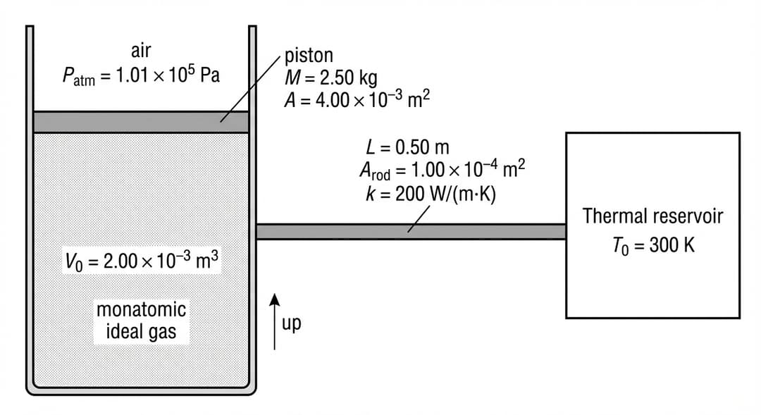
Figure dot. Force diagram. Dot represents the piston (center of mass).

A free-body-diagram template on a blank white background.

Object (required):
- A small solid black dot is centered in the diagram.
- The dot is labeled “piston” with the text placed just below the dot (no box), indicating the dot represents the piston’s center of mass.

Forces to be drawn by the student (the template must make directions unambiguous):
- Include three faint gray placeholder arrows (thin, light) originating exactly at the dot and pointing away from it, showing the ONLY allowed force directions:
  1) One arrow pointing straight upward (vertical up).
  2) One arrow pointing straight downward (vertical down) slightly to the left of the upward arrow so the two labels will not overlap.
  3) A second arrow pointing straight downward (vertical down) slightly to the right of the upward arrow.
- At the tip of each faint arrow, include a small empty label line (blank underline) so students can write the force names; do not pre-fill the force names.

Required relative lengths (to constrain drawing):
- The upward arrow must be the longest arrow.
- The two downward arrows must be shorter than the upward arrow and equal in length to each other.

Context cues (no coordinates):
- Beneath the dot, draw a very short horizontal line segment (thin black) labeled “piston surface is horizontal” to cue that up/down directions are vertical.
- No inclined planes, no axes, and no numerical values.

Note: The template intentionally suggests: one upward force (gas on piston) and two downward forces (atmospheric pressure on piston and weight).
A.

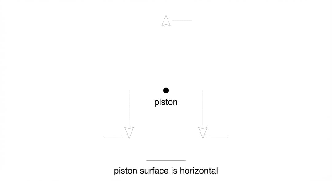
On the dot shown in Figure dot, representing the piston, draw and label the forces that are exerted on the piston. Each force must be represented by a distinct arrow starting on, and pointing away from, the dot.

B.

Derive an expression for the internal energy of the gas in terms of MMM, AAA, V0V_0V0​, PatmP_{\text{atm}}Patm​, and physical constants, as appropriate. Begin your derivation by writing a fundamental physics principle or an equation from the reference information.

Figure 2. Blank pressure–volume axes for sketching the gas process during t0 ≤ t ≤ tf.

A blank P–V graph template with clearly labeled axes on a white background.

Axes appearance and placement:
- The horizontal axis runs left to right across the bottom of the graph area with a right-pointing arrowhead at its far right end.
- The vertical axis runs bottom to top along the left side of the graph area with an upward-pointing arrowhead at its top end.
- The axes intersect at the bottom-left corner of the plotting region, forming a clear origin.

Axis labels (visible text):
- Vertical axis label: “P (Pa)” written parallel to the vertical axis, centered along its height.
- Horizontal axis label: “V (m^3)” written below the horizontal axis, centered along its length.

Tick marks and numbers:
- Include evenly spaced tick marks on both axes, but DO NOT include any numerical tick labels (no numbers). This is required because the prompt provides no pressure or volume plotting range for Figure 2.
- The first tick mark on each axis is placed a short distance from the origin to make the origin visually distinct.

Other requirements:
- No curve is drawn (students will sketch the process).
- No grid lines.
- No title inside the plotting area.
- The plotting area is otherwise empty.
C.

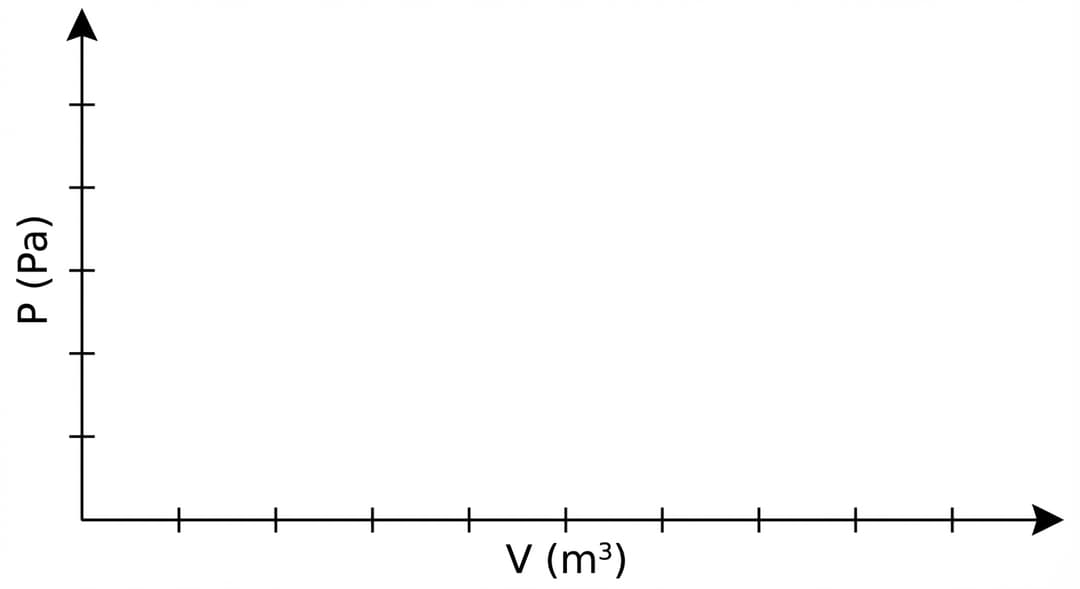
On the axes provided in Figure 2, sketch the expected relationship between the pressure PPP and volume VVV of the gas for the thermodynamic process that the gas undergoes during the time interval t0≤t≤tft_0 ≤ t ≤ t_ft0​≤t≤tf​. Draw an arrow on your sketch to represent the direction of the thermodynamic process. A metal block of mass mb=3.00 kgm_b = 3.00\ \text{kg}mb​=3.00 kg is slowly placed on top of the piston at time t=t0t=t_0t=t0​. The piston moves downward and comes to rest at time t=tft=t_ft=tf​ with the gas in thermal equilibrium with the reservoir at temperature T0T_0T0​.

D.

Indicate whether the entropy change ΔSgas\Delta S_{\text{gas}}ΔSgas​ of the gas during the interval is greater than, less than, or equal to zero. After the block remains on the piston, the thermal reservoir is changed to a new constant temperature Tnew=360 KT_{\text{new}} = 360\ \text{K}Tnew​=360 K while the gas is at volume V=1.80×10⁻³ m3V = 1.80\times10^{-3}\ \text{m}^3V=1.80×10⁻³ m3. For a short time interval, the volume is held constant by a clamp, and energy is transferred only by conduction through the rod. Assume the temperature difference between the reservoir and the gas remains constant at ΔT=Tnew−T=60 K\Delta T = T_{\text{new}}-T = 60\ \text{K}ΔT=Tnew​−T=60 K during the interval of duration Δt=120 s\Delta t = 120\ \text{s}Δt=120 s.

given_values: ["Tnew=360 KT_{\text{new}}=360\ \text{K}Tnew​=360 K", "ΔT=60 K\Delta T=60\ \text{K}ΔT=60 K", "Δt=120 s\Delta t=120\ \text{s}Δt=120 s", "k=200 W/(m\cdotpK)k=200\ \text{W/(m·K)}k=200 W/(m\cdotpK)", "L=0.50 mL=0.50\ \text{m}L=0.50 m", "Arod=1.00×10⁻⁴ m2A_{\text{rod}}=1.00\times10^{-4}\ \text{m}^2Arod​=1.00×10⁻⁴ m2"]

ΔSgas>0\Delta S_{\text{gas}} > 0ΔSgas​>0
ΔSgas<0\Delta S_{\text{gas}} < 0ΔSgas​<0
ΔSgas=0\Delta S_{\text{gas}} = 0ΔSgas​=0

Briefly justify your answer by referencing (i) the direction of energy transfer due to the temperature difference and (ii) at least one representation from your answers to parts A, B, or C.


Pep

essential ap study content awaits..

Features
Testimonials
Testimonials
start studying →
FRQ Directions
Free Response Question Practice

This practice environment simulates the AP AP Physics 2 Free Response Questions section. Here are some guidelines:

  • Read each question carefullybefore responding. Pay attention to command verbs like "identify," "explain," "analyze," or "evaluate."
  • Use the timer to practice time management. You can pause, restart, or hide the timer as needed.
  • Mark for Review if you want to come back to a question later.
  • Your responses are saved automatically as you type. You can also use the drawing tool for questions that require diagrams or graphs.
  • Use the toolbar for formatting options like bold, italic, subscript, and superscript.
  • Navigate between questions using the Previous and Next buttons at the bottom of the screen.

Tip: Answer all parts of each question. Partial credit is often available, so even if you are unsure, provide what you know.