Fiveable
🧲AP Physics 2
​

🧲AP Physics 2

FRQ 3 – Experimental Design
​
Unit 9: Thermodynamics
​
FRQ Types & Units

Each FRQ type tests specific skills taught in particular units. Here's why certain units appear for each question type:

This mapping reflects College Board's exam structure - each FRQ type tests specific skills that are taught in particular units.

Practice FRQ 1 of 51/5

3. In an investigation of the thermodynamic behavior of a gas, a student uses a fixed amount of dry air confined in a cylinder with a movable piston. The student will design an experiment to determine a thermodynamic property of the gas and then analyze a second set of data to determine that property from a graph.

Figure 1. Cylinder-piston apparatus for gas measurement

A clean black-and-white physics apparatus diagram with labeled components and numeric values shown as printed text.

Overall layout (left-to-right):
- The main object is a tall, upright cylinder drawn in the center of the diagram. The cylinder’s axis is perfectly vertical.
- A meterstick is drawn immediately to the left of the cylinder, parallel to the cylinder, spanning from the bottom of the cylinder to above the piston.
- A pressure sensor module is drawn to the right of the cylinder and connected to the cylinder by a short horizontal tube.
- A thermometer probe is shown entering the gas region through the top assembly (not immersed in the water bath).
- Beneath the cylinder is an optional water bath container drawn as a wide open-topped rectangle that the cylinder can sit in.
- An optional insulating sleeve is shown as a removable outer layer around the cylinder wall.

Cylinder and gas region:
- Draw a vertical cylinder with a flat bottom base. The interior of the cylinder is hollow and contains the gas (label inside the cylinder: “dry air”).
- The bottom of the cylinder is the reference level for height measurements. Mark a thin horizontal reference line at the inside bottom surface and label it “h = 0 reference.”

Movable piston:
- A tight-fitting piston disk is drawn inside the cylinder, perpendicular to the cylinder axis (perfectly horizontal). It divides the interior into a lower gas volume and an upper region that is not part of the gas volume.
- The piston is explicitly labeled “movable low-friction piston.”
- The piston’s cross-sectional area is printed as a label next to the piston: “A = 2.50 × 10^-3 m^2”.
- The piston is drawn at a mid-height position in the cylinder (not at the top or bottom), leaving substantial gas space beneath it.

Piston rod, mass hanger, and masses:
- From the center of the piston, draw a thin vertical rod extending upward out of the cylinder.
- At the top of the rod, draw a mass hanger (a small horizontal platform or hook assembly) centered directly above the piston.
- On the hanger, draw a stack of removable slotted masses (three separate disks) aligned vertically. Label the hanger “mass hanger” and label the stack “removable masses.”
- Add a note near the piston/hanger assembly: “Added masses increase external pressure on the gas.”

Meterstick and height measurement h:
- Draw a meterstick directly beside the cylinder on the left, with tick marks at every 1 cm and numeric labels at every 10 cm: “0, 10, 20, 30, …”. The “0” mark is aligned horizontally with the cylinder’s bottom reference level labeled “h = 0 reference.”
- Draw a thin horizontal dashed line from the top surface of the piston to the meterstick to show the reading location.
- Next to this dashed line, label the measured height: “h”.
- Under the cylinder (or near the gas region), print the volume relationship exactly as visible text: “V = A h”.

Pressure sensor (absolute pressure):
- On the right side of the cylinder, draw a small side port at a height that is clearly below the piston (so it communicates with the gas region).
- Connect the side port to a rectangular pressure sensor box via a short horizontal tube.
- Label the box “pressure sensor” and print next to it: “measures absolute gas pressure P”.
- On the face of the sensor box, draw a small digital display rectangle labeled “P” (no numeric reading shown, only the variable label).

Thermometer probe (gas temperature):
- Draw a thin thermometer probe entering from above at a slight angle, with its tip clearly located in the gas region below the piston (not touching the piston or cylinder walls).
- Label it “thermometer probe” and print next to it: “measures gas temperature T”.

Water bath at 300 K:
- Draw an open rectangular container beneath and around the lower portion of the cylinder labeled “water bath.”
- Draw a horizontal waterline across the container and shade the region below it lightly to indicate water.
- Print the temperature label directly on the bath: “300 K water bath”.
- Show the cylinder sitting in the bath so that the waterline reaches roughly halfway up the gas-containing portion of the cylinder (clearly below the piston).

Insulating sleeve:
- Draw a removable sleeve as a second outer wall that surrounds the cylinder on the sides only (not covering the bottom), shown slightly separated from the cylinder wall to indicate it can be added or removed.
- Label this outer layer “insulating sleeve (optional)”.

Forces/pressure clarity:
- Add two arrows: one downward arrow on the top of the piston labeled “external pressure from atmosphere + masses” and one upward arrow from the gas region onto the piston labeled “gas pressure P”.

All labels required to appear as visible text in the diagram:
“A = 2.50 × 10^-3 m^2”, “V = A h”, “h”, “dry air”, “movable low-friction piston”, “mass hanger”, “removable masses”, “pressure sensor”, “measures absolute gas pressure P”, “thermometer probe”, “measures gas temperature T”, “water bath”, “300 K water bath”, “insulating sleeve (optional)”, and “h = 0 reference”.

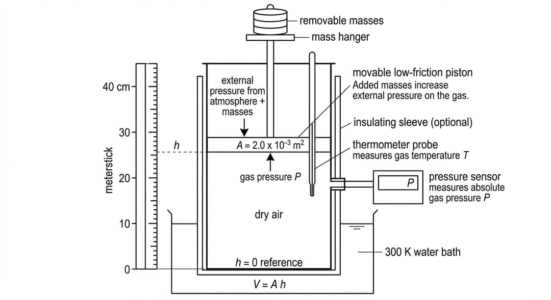
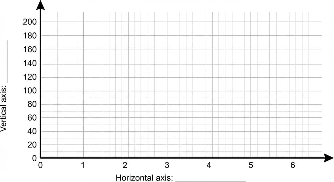
Figure 2. Cartesian grid for moles determination

A blank Cartesian grid designed for hand-plotting and drawing a best-fit straight line, with NO data points pre-plotted.

Grid and axes appearance:
- The grid is a large square plotting area occupying most of the page.
- The horizontal axis is a thick black line along the bottom edge of the grid with an arrowhead pointing to the right.
- The vertical axis is a thick black line along the left edge of the grid with an arrowhead pointing upward.
- The axes intersect at the bottom-left corner of the grid; the intersection is labeled “0” on both axes (single “0” at the origin).
- The interior is filled with evenly spaced light gray grid lines forming square cells.

Tick marks and numeric scales (numbers must be printed on the axes as visible text):
- Horizontal axis tick marks are evenly spaced and labeled: 0, 1, 2, 3, 4, 5, 6.
- Vertical axis tick marks are evenly spaced and labeled: 0, 20, 40, 60, 80, 100, 120, 140, 160, 180, 200.

Axis label blanks (so the student can choose variables):
- The vertical axis has a printed label line (blank) near the middle of the axis reading: “Vertical axis: __________” positioned just to the left of the grid.
- The horizontal axis has a printed label line (blank) centered below the axis reading: “Horizontal axis: __________”.

No other markings:
- No title.
- No legend.
- No plotted points.
- No best-fit line.
- No units printed (since the student selects quantities), other than the numeric tick labels shown above.

Accuracy requirement for spacing:
- The tick labels increase strictly uniformly along each axis: each adjacent pair of labeled ticks on the x-axis differs by exactly 1, and each adjacent pair of labeled ticks on the y-axis differs by exactly 20.
- The grid extends slightly beyond the highest labeled y tick so the “200” label is not on the border, and extends slightly beyond the “6” tick so the arrowhead is beyond the last tick label.
A.

Describe a procedure for collecting data that would allow the student to determine the number of moles n of gas in the cylinder. In your description, include the measurements to be made. Include any steps necessary to reduce experimental uncertainty.

B.

Describe how the collected data could be analyzed to determine n. Include references to appropriate equations and to relationships between measured and known quantities.

P (kPa)

V (x10^-4 m^3)

120

6.24

140

5.35

160

4.68

180

4.16

200

3.74

C.

In a second experiment, the student places the cylinder in the 300 K water bath and waits until the gas reaches thermal equilibrium at T = 300 K for each trial. The student then changes the external load on the piston and records the equilibrium pressure P and volume V of the gas. Table 1 shows the collected data.

i.

Indicate two quantities, either measured quantities from Table 1 or additional calculated quantities, that could be graphed to produce a straight line that could be used to determine n.

Vertical axis: Horizontal axis:

ii.

On the grid provided, create a graph of the quantities indicated in part C(i) that can be used to determine n.

•

Use Table 2 to record the data points or calculated quantities that you will plot.

•

Clearly label the axes, including units as appropriate.

•

Plot the points you recorded in Table 2.

iii.

Draw a best-fit line for the data graphed in part C(ii).

D.

Using the best-fit line that you drew in part C(iii), calculate an experimental value for the number of moles n of the gas. Use R = 8.31 J/(mol·K) and T = 300 K.


Pep

essential ap study content awaits..

Features
Testimonials
Testimonials
start studying →
FRQ Directions
Free Response Question Practice

This practice environment simulates the AP AP Physics 2 Free Response Questions section. Here are some guidelines:

  • Read each question carefullybefore responding. Pay attention to command verbs like "identify," "explain," "analyze," or "evaluate."
  • Use the timer to practice time management. You can pause, restart, or hide the timer as needed.
  • Mark for Review if you want to come back to a question later.
  • Your responses are saved automatically as you type. You can also use the drawing tool for questions that require diagrams or graphs.
  • Use the toolbar for formatting options like bold, italic, subscript, and superscript.
  • Navigate between questions using the Previous and Next buttons at the bottom of the screen.

Tip: Answer all parts of each question. Partial credit is often available, so even if you are unsure, provide what you know.