AP exam review verified for 2027

AP Physics 2 Unit 13 Review: Geometric Optics

Review AP Physics 2 Unit 13 to build fluency with the ray model of light, reflection from mirrors, refraction at boundaries, and image formation by lenses. This unit carries 12-15% of the exam and requires both diagram skills and quantitative problem-solving with the mirror and thin-lens equations.

Use the topic guides, practice questions, and FRQ practice available for all four topics to work through ray diagrams and equation-based problems.

What is AP Physics 2 unit 13?

Geometric optics treats light as traveling in straight lines called rays. This model is valid when the wave nature of light can be ignored, which is the case for reflection and refraction at surfaces but not for interference or diffraction (covered in Unit 14). Unit 13 applies the ray model to mirrors and lenses to predict where images form, what size they are, and whether they are real or virtual.

Unit 13 is about how light rays reflect off mirrors and refract through lenses to form images. You use ray diagrams and two core equations, 1/so + 1/si = 1/f and M = -si/so, along with Snell's law n1 sin theta1 = n2 sin theta2, to solve problems about image location, size, and orientation.

The ray model and reflection

A light ray is a straight line perpendicular to the wavefront. The law of reflection states that the angle of incidence equals the angle of reflection, both measured from the normal. Specular reflection occurs at smooth surfaces; diffuse reflection occurs at rough surfaces where the normal direction varies.

Mirrors and image formation

Concave mirrors converge parallel rays to a real focal point; convex mirrors diverge them to a virtual focal point behind the mirror. The mirror equation 1/so + 1/si = 1/f and magnification M = -si/so determine image location and size. Sign conventions distinguish real from virtual images and upright from inverted orientations.

Refraction and lenses

Refraction occurs because light changes speed at a boundary, quantified by the index of refraction n = c/v. Snell's law n1 sin theta1 = n2 sin theta2 predicts the bending direction. When light moves from a denser to a less dense medium at an angle exceeding the critical angle, total internal reflection occurs. Converging and diverging lenses use refraction to form images described by the same thin-lens equation form as the mirror equation.

Why objects are not always where they appear

Reflection and refraction both cause light to change direction, so the apparent position of an object seen through a mirror or lens differs from its actual position. This is the central insight of geometric optics: image location is determined by tracing rays through the optical system, not by assuming light travels in a straight line from object to eye.

AP Physics 2 unit 13 topics

13.1

Reflection

Models light as a ray perpendicular to the wavefront. Applies the law of reflection (theta_i = theta_r) and distinguishes specular reflection from smooth surfaces and diffuse reflection from rough surfaces. Introduces ray diagrams as the core tool for geometric optics.

open guide
13.2

Images Formed by Mirrors

Uses the mirror equation 1/so + 1/si = 1/f and magnification M = -si/so to find image location, size, and orientation for concave, convex, and plane mirrors. Ray diagrams with three principal rays confirm algebraic results.

open guide
13.3

Refraction

Explains refraction as a speed change at a boundary, quantified by n = c/v. Applies Snell's law to predict bending direction and calculates the critical angle for total internal reflection when light moves from a denser to a less dense medium.

open guide
13.4

Images Formed by Lenses

Applies the thin-lens equation and magnification to converging and diverging lenses. Converging lenses can form real or virtual images; diverging lenses always form virtual, upright, reduced images. Ray diagrams use three principal rays through the lens.

open guide
practice snapshot

Hardest AP Physics 2 unit 13 topics

This snapshot uses Fiveable practice activity to show where students tend to miss questions and which review moves are worth prioritizing first.

59%average MCQ accuracy

Across 582 multiple-choice practice attempts for this unit.

582MCQ attempts

Practice activity included in this snapshot.

58%average FRQ score

Across 4 scored free-response attempts for this unit.

Hardest topics in unit 13

MCQ miss rate
13.4

Review Images Formed by Lenses with attention to how the concept appears in AP-style source and evidence questions.

48%175 tries
13.3

Review Refraction with attention to how the concept appears in AP-style source and evidence questions.

43%120 tries
13.1

Review Reflection with attention to how the concept appears in AP-style source and evidence questions.

42%163 tries
13.2

Review Images Formed by Mirrors with attention to how the concept appears in AP-style source and evidence questions.

31%124 tries

Unit 13 review notes

13.1

The Ray Model and Reflection

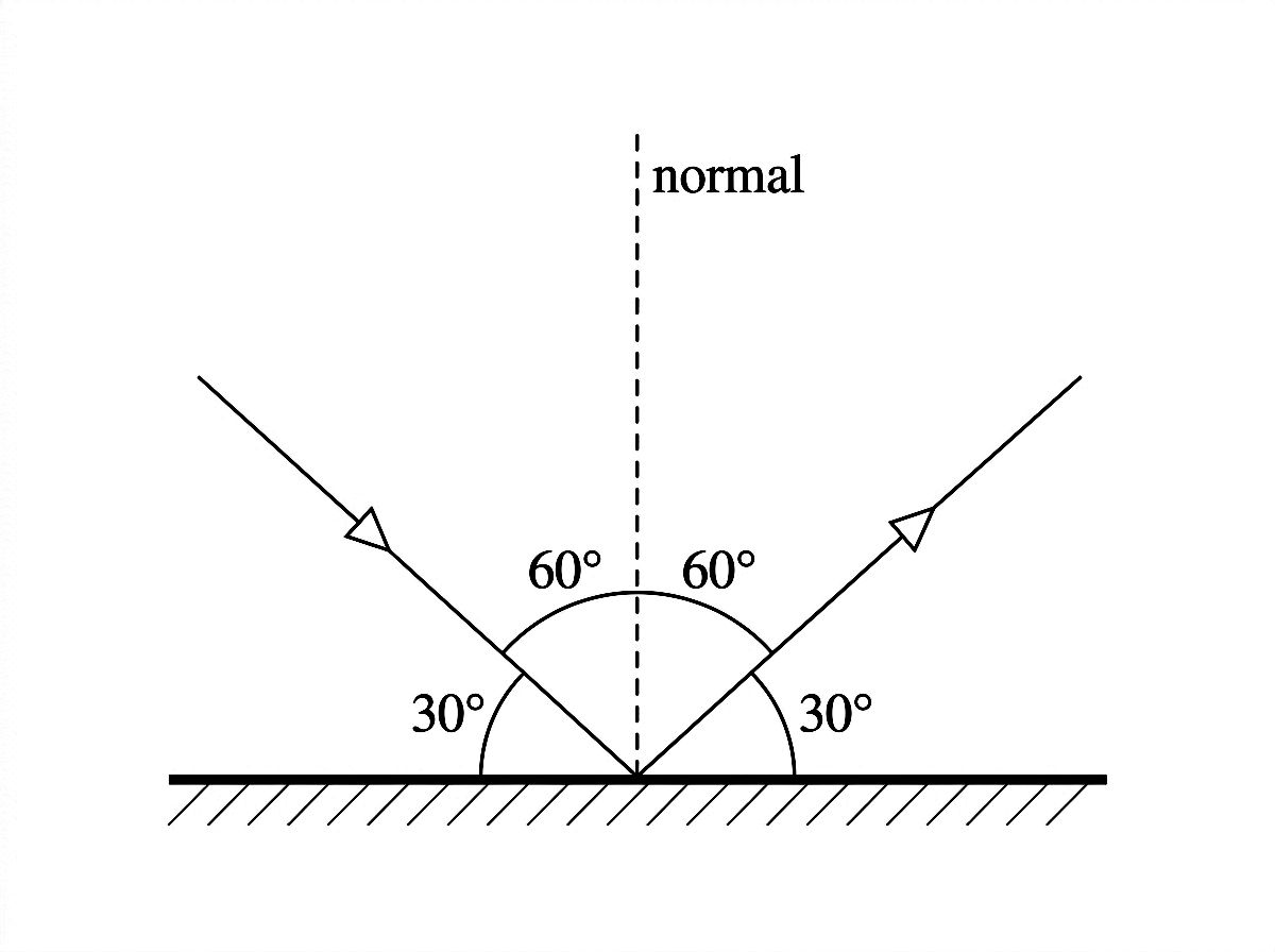
A light ray is a straight line perpendicular to the wavefront, pointing in the direction of wave travel. In geometric optics, the wave nature of light is ignored, so rays travel in straight lines until they hit a surface. A laser is a practical example of a single coherent, monochromatic beam that can be modeled as a ray. When a ray strikes a surface, the law of reflection applies: the angle of incidence equals the angle of reflection, both measured from the normal to the surface at the point of contact.

  • Law of reflection: theta_i = theta_r; both angles measured from the normal, not the surface.
  • Specular reflection: Occurs at smooth surfaces where the normal direction is constant; produces clear, mirror-like images.
  • Diffuse reflection: Occurs at rough surfaces where the normal varies across the surface; light scatters in many directions.
  • Ray diagram: A diagram using straight lines to show the path of light before and after interacting with a surface or optical element.
  • Limits of the ray model: Rays cannot explain interference or diffraction; those phenomena require treating light as a wave (Unit 14).
Draw a ray hitting a flat surface at 35 degrees from the normal. Identify the incident ray, reflected ray, and normal, and label both angles.
TypeSurfaceReflected raysResult
SpecularSmoothAll parallelClear image
DiffuseRoughMany directionsScattered light, no clear image
13.2

Images Formed by Mirrors

Spherical mirrors form images by reflecting light according to the law of reflection. The focal length f equals half the radius of curvature R. The mirror equation 1/so + 1/si = 1/f relates object distance, image distance, and focal length. Magnification M = -si/so gives the ratio of image height to object height and indicates orientation. A positive si means a real image forms in front of the mirror; a negative si means a virtual image forms behind it. Ray diagrams use three principal rays to locate images: the ray parallel to the principal axis, the ray through the focal point, and the ray through the center of curvature.

  • Concave mirror: Converging mirror; parallel rays reflect toward the real focal point in front of the mirror. f is positive.
  • Convex mirror: Diverging mirror; parallel rays reflect as if from a virtual focal point behind the mirror. f is negative.
  • Mirror equation: 1/so + 1/si = 1/f; use consistent sign conventions (real images have positive si for mirrors).
  • Magnification: M = -si/so; negative M means inverted image, |M| > 1 means enlarged.
  • Plane mirror: Flat mirror with f at infinity; always forms an upright, virtual image the same size as the object, located as far behind the mirror as the object is in front.
An object is placed 30 cm in front of a concave mirror with f = 10 cm. Use the mirror equation to find si and M, then state whether the image is real or virtual and upright or inverted.
Mirror typef signImage type (object outside f)Image orientationImage size
Concave (object outside f)PositiveRealInvertedVaries with position
Concave (object inside f)PositiveVirtualUprightEnlarged
ConvexNegativeVirtualUprightReduced
PlaneInfiniteVirtualUprightSame size
13.3

Refraction and Total Internal Reflection

Refraction is the change in direction of a light ray as it crosses from one medium into another, caused by the change in the speed of light. The index of refraction n = c/v quantifies how much slower light travels in a medium compared to a vacuum. Snell's law n1 sin theta1 = n2 sin theta2 predicts the angle of refraction. When light moves from a medium with higher n to one with lower n, it bends away from the normal. If the angle of incidence exceeds the critical angle theta_c = sin^-1(n2/n1), no light is transmitted and total internal reflection occurs. This principle underlies optical fiber technology.

  • Index of refraction: n = c/v; higher n means slower light and more bending at a boundary.
  • Snell's law: n1 sin theta1 = n2 sin theta2; angles measured from the normal at the boundary.
  • Bending direction: Light bends toward the normal when entering a denser medium (higher n); away from the normal when entering a less dense medium.
  • Critical angle: theta_c = sin^-1(n2/n1); only defined when n1 > n2. At or beyond this angle, total internal reflection occurs.
  • Total internal reflection: All incident light reflects back into the denser medium; no refracted ray exits. Used in optical fibers.
Light travels from glass (n = 1.5) into air (n = 1.0) at an angle of incidence of 25 degrees. Use Snell's law to find the angle of refraction, then calculate the critical angle for this glass-air interface.
Conditionn1 vs n2Ray bendsPossible outcome
Low to high nn1 < n2Toward normalRefraction only
High to low n, below critical anglen1 > n2Away from normalRefraction only
High to low n, at or above critical anglen1 > n2No transmitted rayTotal internal reflection
13.4

Images Formed by Lenses

Thin lenses form images by refracting light at two surfaces. A converging (convex) lens brings parallel rays to a real focal point on the transmitted side. A diverging (concave) lens spreads parallel rays as if they came from a virtual focal point on the incident side. The thin-lens equation 1/so + 1/si = 1/f has the same form as the mirror equation, and magnification M = -si/so applies with the same sign interpretation. For lenses, a positive si means a real image on the opposite side from the object; a negative si means a virtual image on the same side as the object. Ray diagrams use three principal rays: the ray parallel to the axis refracts through the far focal point, the ray through the near focal point emerges parallel, and the ray through the lens center passes undeviated.

  • Converging lens: Convex lens with positive f; can form real or virtual images depending on object position relative to f.
  • Diverging lens: Concave lens with negative f; always forms a virtual, upright, reduced image regardless of object position.
  • Thin-lens equation: 1/so + 1/si = 1/f; same form as the mirror equation but sign conventions differ for real/virtual images.
  • Magnification: M = -si/so; negative means inverted, positive means upright, |M| > 1 means enlarged.
  • Object at focal point: When so = f for a converging lens, refracted rays are parallel and no image forms (si approaches infinity).
An object is 20 cm from a converging lens with f = 15 cm. Find si and M. Is the image real or virtual? Upright or inverted?
Lens typef signObject positionImage typeOrientation
ConvergingPositiveBeyond fRealInverted
ConvergingPositiveInside fVirtualUpright
DivergingNegativeAnyVirtualUpright

Practice AP Physics 2 unit 13 questions

Try stimulus-based AP practice questions and written prompts after you review the notes.

Example stimulus-based MCQs

open all practice
diagram

Stimulus-based practice question

diagram

Monochromatic light in air is incident on the flat surface of a semicircular glass block (n = 1.5) at the center of the flat face. The figure shows four rays—labeled A, B, C, and D—striking the curved surface from inside the glass at different angles of incidence: 10°, 30°, 42°, and 55° respectively.

Question

The critical angle for this glass-air interface is approximately 42°. Which of the following correctly compares the behavior of Ray B (30°) and Ray D (55°) at the curved surface?

Ray B refracts into the air and bends away from the normal; Ray D undergoes total internal reflection and no light exits.

Ray B refracts into the air and bends toward the normal; Ray D undergoes total internal reflection and no light exits.

Ray B refracts into the air and bends away from the normal; Ray D also refracts into the air but at a very large angle near 90°.

Both Ray B and Ray D undergo total internal reflection because both rays originate inside the glass.

diagram

Stimulus-based practice question

diagram

A student sets up a laser and directs it at a flat mirror, as shown. The laser beam strikes the mirror surface at an angle of 30° measured from the mirror surface. The student claims the reflected beam makes an angle of 30° with the mirror surface on the other side of the normal.

Question

Which option best evaluates the student's claim?

Correct, because 30° from the surface means 60° from the normal.

Incorrect, because reflection angles are measured from the surface, not the normal.

Incorrect, because the reflected ray makes 60° with the mirror surface.

Correct, because equal reflection angles are measured from the mirror surface.

Example FRQs

open all FRQs
FRQ

Concave mirror image formation and location

1. A small object is placed in front of a concave spherical mirror on the principal axis. The mirror has focal length fm=12.0 cmf_m = 12.0\ \text{cm} and the object is placed a distance do,m=30.0 cmd_{o,m} = 30.0\ \text{cm} from the mirror. A ray diagram is to be used with the approximation that light travels as rays and that the mirror is spherical with a small aperture. The mirror is initially in air (nair=1.00)\left(n_{air} = 1.00\right). A single incident light ray from the top of the object strikes the mirror at a point where the normal to the mirror surface makes an angle θi=35.0\theta_i = 35.0^\circ with the incident ray, as shown in Figure 1.

Figure 1. Concave spherical mirror in air with an object on the principal axis and a single incident ray striking the mirror at a specified angle to the local normal.

Ray-optics setup diagram (no graph axes).

Overall layout and reference line:
- Draw one straight horizontal line across the full width of the figure as the principal axis. Label it "principal axis" near the center of the line.
- Place the concave spherical mirror on the right side of the figure. Represent the mirror as a vertical arc (a parenthesis-shaped curve) opening toward the left, with the mirror’s reflecting surface facing left.
- Mark the mirror vertex (the point where the mirror intersects the principal axis) with a small dot on the principal axis and label it "V".

Given distances shown explicitly on the axis:
- Place the object on the principal axis to the left of the mirror: draw an upright vertical arrow whose base sits exactly on the principal axis. Label the arrow "Object".
- Between the object base and the mirror vertex V, draw a double-headed horizontal dimension arrow along the principal axis and label it exactly "d_{o,m} = 30.0 cm".
- Mark the focal point on the principal axis between the object and the mirror: place a small point on the axis left of V and label it "F".
- Between F and V, draw a separate double-headed dimension arrow along the principal axis labeled exactly "f_m = 12.0 cm".

Incident ray and point of incidence:
- From the top tip of the object arrow, draw a single straight incident ray heading rightward toward the mirror.
- The ray must strike the mirror above the principal axis at a clearly indicated point of incidence on the mirror surface; mark this point with a small solid dot and label it "P" (for point of incidence).

Normal and angle specification (must be unambiguous):
- At point P, draw the local normal as a straight line that passes through P and points inward toward the mirror’s center of curvature direction (i.e., it is perpendicular to the mirror surface at P). Label this line "normal".
- At point P, draw a curved angle marker between the incident ray segment (approaching P) and the normal line.
- Label that angle marker exactly "θ_i = 35.0°".
- Ensure the angle is clearly the angle between the incident ray and the normal (not the angle to the surface). The angle arc should be drawn on the incident side, opening from the normal toward the incident ray.

Medium label:
- In an open area of the diagram (e.g., above the principal axis), add the text "air (n_air = 1.00)" to indicate the surrounding medium.

Line/label clarity requirements:
- Use arrowheads on the incident ray to show propagation direction toward the mirror.
- All labels (V, F, Object, P, normal, θ_i = 35.0°, d_{o,m} = 30.0 cm, f_m = 12.0 cm, air (n_air = 1.00)) must be legible and not overlapping.

Figure 2. Close-up of incidence at the concave mirror showing incident ray, local normal, and space to add the reflected ray.

Enlarged reflection-at-a-point diagram (no principal-axis distances).

Frame and main reference point:
- Show only a small portion of the concave mirror surface as a smooth curved arc located on the right side of this figure, with the reflecting surface facing left.
- Mark a single point of incidence on the mirror surface with a solid dot near the middle of the figure and label it "P".

Given rays/lines (must already be drawn):
- Draw the incident ray as a straight line approaching P from the left side of the figure. Put an arrowhead on the ray pointing toward P to indicate direction of travel.
- Draw the normal line at P as a straight line passing through P and perpendicular to the mirror surface at P. Extend the normal line on both sides of P so its direction is visually clear. Label it "normal".

Angle marking (exact numerical value):
- Draw a curved angle marker at P between the incident ray and the normal on the incident side.
- Label the angle exactly "θ_i = 35.0°".

Student response area (reflected ray not pre-drawn):
- Do NOT draw the reflected ray.
- Leave clear empty space on the side of P opposite the incident ray direction so a reflected ray can be drawn starting at P.
- Add a small text prompt near that empty space: "Draw reflected ray".

Style constraints:
- Ensure the incident ray and the normal are darker/thicker than the mirror arc so the angle is easy to interpret.
- No extra rays, no focal point, and no object should appear in this close-up.

Figure 3. Principal-axis ray diagram layout for a concave mirror with the object placed at 30.0 cm and focal point at 12.0 cm; space provided to mark the image location and orientation.

Principal-axis mirror diagram for image formation (no lens, no slab, no screen).

Principal axis and mirror:
- Draw a single straight horizontal line across the full width as the principal axis.
- On the right side, draw the concave spherical mirror as a vertical arc opening to the left.
- Mark the mirror vertex where the mirror meets the axis with a dot labeled "V".

Object placement with exact given distance:
- On the principal axis to the left of V, draw an upright vertical arrow with its base exactly on the principal axis and label it "Object".
- Draw a double-headed dimension arrow along the principal axis from the object base to V labeled exactly "d_{o,m} = 30.0 cm".

Focal point placement with exact given distance:
- Mark a point on the principal axis between the object and V labeled "F".
- Draw a double-headed dimension arrow along the axis from F to V labeled exactly "f_m = 12.0 cm".

Image-response region (must be blank for student work):
- Do NOT draw the image arrow.
- Leave an open, uncluttered region on the principal axis between the object and the mirror and also to the left of the object so the student can place the image at the correct location.
- Include the text instruction near the open region: "Indicate image location and label upright/inverted".

Optional reference points for clarity (allowed but not rays):
- You may include a faint tick mark at F and at V to make them distinct from the axis.
- Do NOT draw any principal rays in this figure (no parallel ray, no focal ray) so that only the placement task remains.

All visible text must match exactly: "V", "F", "Object", "d_{o,m} = 30.0 cm", "f_m = 12.0 cm".
A.
i.

Complete the following tasks in Figures 2 and 3.

In Figure 2, Indicate the direction of the reflected ray from the mirror.

In Figure 3, Indicate the location of the image formed by the mirror and whether the image is upright or inverted.

ii.

The object has height ho=3.00 cmh_o = 3.00\ \text{cm}.

Derive an expression for the image distance di,md_{i,m} and the image height hi,mh_{i,m} formed by the mirror in terms of fmf_m, do,md_{o,m}, and hoh_o. Begin your derivation by writing a fundamental physics principle or an equation from the reference information.

Figure 4. Mirror–lens–screen system with a plane-parallel slab (n_s = 1.50, thickness 4.00 cm) inserted between the mirror and lens at normal incidence.

Combined optical system diagram along one principal axis (mirror + slab + thin lens + screen).

Principal axis and left-to-right order (must be exact):
- Draw a single straight horizontal line across the figure as the principal axis.
- Place the concave mirror on the far left side of this figure’s optical train or, if you prefer continuity with prior figures, place it on the left side with its reflecting surface facing right-to-left? (No—must match earlier: mirror facing left.) Therefore: place the concave mirror on the left side of the optical train but still drawn as an arc opening to the left, meaning reflected rays travel leftward; however the prompt states the lens is to the right so reflected light passes through the lens, implying reflected rays go to the right. To remove ambiguity, draw the mirror on the left side with its reflecting surface facing right (arc opening to the right) so reflected rays propagate rightward toward the lens.

Mirror and medium label:
- Mark the mirror vertex on the axis with a dot labeled "V".
- In the region between mirror and lens, include the text "air (n_air = 1.00)".

Lens placement with exact separation from mirror:
- Draw a thin converging lens as a vertical line on the principal axis to the right of the mirror.
- Label the lens "Converging lens".
- Between the mirror vertex V and the lens center (the intersection of the lens line and the principal axis), draw a double-headed dimension arrow along the principal axis labeled exactly "L = 60.0 cm".
- Near the lens, add text "f_L = 20.0 cm".

Screen placement with exact separation from lens:
- To the right of the lens, draw a vertical screen as a thicker vertical line segment intersecting the principal axis.
- Label it "Screen".
- Between the lens center and the screen line, draw a double-headed dimension arrow along the principal axis labeled exactly "x_s = 30.0 cm".

Plane-parallel slab (normal incidence) with exact thickness and index:
- Between the mirror and the lens, draw a rectangular slab whose two faces are vertical and perpendicular to the principal axis (so rays on the principal axis strike at normal incidence).
- The slab must span fully above and below the principal axis (taller than the ray bundle region) so it is clearly intersected by the rays.
- Indicate its thickness along the principal axis by drawing a double-headed dimension arrow from the left face of the slab to the right face of the slab and label it exactly "t = 4.00 cm".
- Inside the slab rectangle, write "n_s = 1.50".

Ray path indication (minimal, to show direction only):
- Draw one or two representative rays traveling from the mirror toward the right, passing straight through the slab (no bending at the faces because incidence is normal), then continuing to the lens and toward the screen.
- Put arrowheads on the rays to show propagation from mirror → lens → screen.

Clarity constraints:
- Do not include any additional focal points or image markers unless explicitly labeled.
- All numeric labels must appear exactly as: "L = 60.0 cm", "f_L = 20.0 cm", "x_s = 30.0 cm", "t = 4.00 cm", "n_s = 1.50", "n_air = 1.00".
B.

Indicate whether a sharp image forms on the screen, forms in front of the screen, forms behind the screen, or no real image forms. The mirror remains in air. A thin converging lens of focal length fL=20.0 cmf_L = 20.0\ \text{cm} is placed on the principal axis a distance L=60.0 cmL = 60.0\ \text{cm} to the right of the mirror, as shown in Figure 4. A plane-parallel slab with index of refraction ns=1.50n_s = 1.50 and thickness t=4.00 cmt = 4.00\ \text{cm} is inserted between the mirror and the lens so that the rays pass through the slab at normal incidence. A screen is placed a distance xs=30.0 cmx_s = 30.0\ \text{cm} to the right of the lens.

Sharp image on the screen
Image forms in front of the screen
Image forms behind the screen
No real image forms

Justify your answer.

FRQ

Light reflection, refraction, and lens imaging

2. A narrow beam of red light (wavelength in air λ=650 nm\lambda = 650\ \text{nm}) is modeled as a ray. The ray travels in air and strikes a flat plane mirror at point P. The mirror is oriented so that the normal at P is in the plane of the page. The incident ray makes an angle of 3535^\circ with the normal. After reflecting from the mirror, the ray travels through air toward a transparent semicircular block of radius R=8.0 cmR = 8.0\ \text{cm}. The ray enters the block through the curved surface along a radius directed toward the center of curvature, so the ray is incident normally on the curved surface. The block has index of refraction n=1.50n = 1.50. The ray then reaches the flat face of the block and emerges back into air. The reflected and refracted rays then pass through a thin converging lens of focal length f=10.0 cmf = 10.0\ \text{cm}. An object (a small arrow) of height ho=2.0 cmh_o = 2.0\ \text{cm} is placed on the principal axis at a distance do=15.0 cmd_o = 15.0\ \text{cm} to the left of the lens, as shown in Figure 1.

Figure 1. Reflection from a plane mirror, refraction through a semicircular block, then imaging by a converging thin lens (all distances and angles labeled).

A single-page, black-line optics setup diagram (no graph axes). All rays are straight with clear arrowheads indicating direction of light travel from left to right overall.

PAGE LAYOUT (left to right):
1) Plane mirror and reflection region occupy the left quarter of the page.
2) Semicircular block occupies the middle of the page.
3) Thin converging lens and object-arrow occupy the right quarter of the page.

1) PLANE MIRROR WITH POINT P AND NORMAL:
- Draw a plane mirror as a straight vertical line segment (mirror surface line), located near the left margin. The mirror line is perfectly vertical.
- Mark a distinct point on the mirror line at its vertical midpoint; label this point clearly as “P”.
- At point P, draw a dashed normal line that is perfectly horizontal (left–right) and passes through P. Label this dashed line “normal”.
- Incident ray in air: draw a straight ray approaching P from the upper-left side of the page. The ray must meet the mirror exactly at P. Place an arrowhead on the incident ray pointing toward P.
- Angle marking: between the incident ray and the dashed normal on the incident side, draw a curved angle arc and label it “35°”. Place the label next to the arc. Also label the angle as “θ_i” next to the same arc (so the arc is labeled both “θ_i” and “35°” in readable text).
- Reflected ray in air: from P, draw a straight ray leaving to the upper-right side of the page (symmetric with the incident ray about the dashed horizontal normal). Place an arrowhead on the reflected ray pointing away from P toward the right.
- Angle marking: between the reflected ray and the dashed normal on the reflected side, draw a curved angle arc that is congruent to the incidence arc and label it “35°”. Also label this angle as “θ_r”.
- Ensure the geometry visually enforces θ_i = θ_r and both are exactly 35° measured from the normal (not from the mirror).

2) SEMICIRCULAR BLOCK (R = 8.0 cm, n = 1.50) AND REFRACTION PATH:
- To the right of the mirror, draw a semicircular transparent block. The flat face of the block is a vertical straight line segment on the right side of the semicircle; the curved surface is on the left side.
- The semicircle must be drawn so that its diameter is a vertical line that coincides exactly with the flat face: the flat face is the diameter line of the semicircle.
- Label the flat face with the text “flat face” placed just to the right of it.
- Label the curved surface with the text “curved surface” placed just to the left of the arc.
- Mark the center of curvature at the midpoint of the flat face (midpoint of the diameter). Indicate this point with a small dot and label it “center”.
- Draw a radius line from the center to the leftmost point of the curved arc; label this radius “R = 8.0 cm”. The radius line is horizontal, pointing left from the center to the arc.
- Add a material label inside the block: “n = 1.50”.

RAY ENTRY CONDITION (NORMAL INCIDENCE ON CURVED SURFACE):
- Extend the reflected ray from the mirror so it travels toward the semicircular block.
- The reflected ray must strike the curved surface at the leftmost point of the semicircle (the point where the horizontal radius meets the curved arc). This guarantees the incoming ray is along the radius.
- At the entry point on the curved surface, draw the radius from the center to that entry point as a solid line (if not already visible) and ensure the ray overlaps this radius line exactly at the surface, showing normal incidence.
- At this curved-surface entry point, do NOT draw a refraction bend; the ray continues straight into the block along the same line.

INSIDE THE BLOCK TO THE FLAT FACE:
- Inside the block, continue the ray as a straight line from the curved entry point to the flat face.
- The internal ray must intersect the flat face at a point above the center (in the upper half of the flat face), making a clearly nonzero angle with the normal to the flat face.
- At the flat face, draw a dashed normal line that is perfectly horizontal (perpendicular to the vertical flat face) passing through the point where the internal ray hits. Label this dashed line “normal to flat face”.
- Label the angle between the internal ray and this dashed normal as “θ_block” using a curved angle arc drawn on the inside (block) side of the flat face.

EMERGENCE BACK INTO AIR:
- From the same point on the flat face, draw the refracted emerging ray in air on the right side of the flat face. The ray must bend away from the normal compared with the internal ray (since it goes from n = 1.50 to air). Show this by drawing the outgoing ray at a larger angle from the horizontal dashed normal than the internal ray had.
- Place an arrowhead on the emerging ray pointing rightward away from the block.
- Label the angle between the emerging ray and the dashed normal (on the air side) as “θ_air” with a curved angle arc on the air side.

3) THIN CONVERGING LENS, PRINCIPAL AXIS, AND OBJECT ARROW:
- Draw a long straight horizontal line across the right half of the page passing through the center of the lens; label it “principal axis”.
- Place a thin converging lens on this axis to the right of the semicircular block. Represent the lens as a vertical line with small outward arrowheads or the label “converging lens”. Center of the lens lies exactly on the principal axis.
- Label the lens with “f = 10.0 cm” placed near the lens.
- Ensure the ray emerging from the semicircular block is drawn heading toward the lens and passes through the region of the lens (it may cross the principal axis before or after the lens; the key is it clearly reaches the lens).

OBJECT ARROW SPECIFICATIONS:
- Place an upright object arrow on the principal axis to the left of the lens (same horizontal axis line), with its base exactly on the principal axis and arrow pointing upward.
- Label the object “object”.
- Next to the arrow, label its height “h_o = 2.0 cm”.
- Draw a double-headed horizontal dimension arrow along the principal axis from the object base to the lens center and label it “d_o = 15.0 cm”.

LIGHT LABELING:
- Near the incident ray region (air), include a text label “λ = 650 nm (air)”.

STYLE CONSTRAINTS:
- Use solid black lines for mirror, block boundaries, lens, and rays.
- Use dashed lines only for normals.
- All labels are printed text. Angle arcs are clearly visible and unambiguous.

Figure dot. Ray diagram space for Part A (reflection at point P).

A clean, uncluttered reflection-only diagram with large blank space for student drawing.

MIRROR AND POINT P:
- Draw a plane mirror as a straight vertical line segment positioned slightly left of center on the page.
- Mark point “P” at the vertical midpoint of the mirror line with a filled dot and the label “P” immediately next to the dot.

NORMAL AT P:
- Through P, draw a dashed normal line that is perfectly horizontal and extends well to both left and right of the mirror. Label the dashed line “normal”.

INCIDENT RAY (GIVEN):
- Draw a single incident ray as a straight solid line coming from the upper-left region of the page down toward P. The ray must terminate exactly at P.
- Put one arrowhead on the ray pointing toward P.
- Place a curved angle arc between the incident ray and the dashed normal on the incident (left) side of the mirror.
- Label this arc with two pieces of text: “θ_i” and “35°”, both clearly associated with the same arc.

BLANK SPACE FOR STUDENT WORK:
- Do not draw the reflected ray.
- Leave the entire region to the right of the mirror mostly blank, with enough room to draw a reflected ray leaving P.
- Leave space near the right side of the normal for an angle arc and label “θ_r” and “35°” to be added by students.

STYLE:
- Solid black lines for mirror and incident ray; dashed line for the normal; no other optics elements; no grid; no axes; no extra numbers.
A.

On the diagram provided (see Figure dot), draw and label the reflected ray from the plane mirror at point P. Clearly label the angle of incidence θi\theta_i and the angle of reflection θr\theta_r measured from the normal, and indicate their numerical values in degrees.

B.

Derive an expression for the angle θair\theta_{\text{air}} (measured from the normal to the flat face) at which the ray emerges into air from the flat face of the semicircular block in terms of nn and the angle θblock\theta_{\text{block}} at which the ray inside the block strikes the flat face. Begin your derivation by writing a fundamental physics principle or an equation from the reference information.

Figure 2. Principal-axis ray diagram workspace for a thin converging lens (f = 10.0 cm) with object at d_o = 15.0 cm.

A ray-diagram workspace with a single horizontal principal axis, a thin converging lens at the center, labeled focal points, and a correctly scaled distance marking for the object. No pre-drawn rays beyond the object itself.

AXIS AND SCALE:
- Draw one long horizontal line across most of the page width; label it beneath the line at center as “principal axis”.
- Place evenly spaced tick marks along the principal axis.
- Put a numeric scale directly on the axis: label the lens center tick as “0 cm”.
- To the left of the lens, label ticks at “-5 cm”, “-10 cm”, “-15 cm”, “-20 cm”.
- To the right of the lens, label ticks at “+5 cm”, “+10 cm”, “+15 cm”, “+20 cm”.
- The spacing between each 5 cm tick interval is identical on both sides (uniform linear scale).

LENS:
- At the “0 cm” position, draw a thin converging lens as a vertical line segment intersecting the principal axis. Add small outward-pointing arrows on the line or label it clearly “converging lens”.
- Label near the lens: “f = 10.0 cm”.

FOCAL POINTS:
- Mark the left focal point exactly at the “-10 cm” tick with a small dot and label it “F”.
- Mark the right focal point exactly at the “+10 cm” tick with a small dot and label it “F”.

OBJECT ARROW:
- At the “-15 cm” tick, draw an upright object arrow with its base exactly on the principal axis and its tip pointing straight up.
- Label the arrow “object”.
- Next to the object arrow, label “h_o = 2.0 cm”.

WORKSPACE FOR RAYS AND IMAGE:
- Do not draw any rays through the lens.
- Leave clear blank space above and below the principal axis, especially between the object and lens and to the right of the lens, for students to draw at least two principal rays and the image.

STYLE:
- Black lines, no grid, no shading. All text labels are readable and placed so they do not overlap the axis or lens.
C.

On the axes provided (see Figure 2), sketch a ray diagram for the converging lens showing at least two principal rays from the top of the object that pass through the lens and form the image. Draw and label the image, and indicate whether the image is real or virtual and whether it is upright or inverted. Assume the ray that reaches the lens can be treated as part of the light from the object. The lens is thin and in air, and the object is on the principal axis.

D.

Indicate whether the image distance did_i for the lens is greater than, less than, or equal to 20.0 cm20.0\ \text{cm}. Use f=10.0 cmf = 10.0\ \text{cm}, do=15.0 cmd_o = 15.0\ \text{cm}, and ho=2.0 cmh_o = 2.0\ \text{cm}.

given_values:

  • f=10.0 cmf = 10.0\ \text{cm}
  • do=15.0 cmd_o = 15.0\ \text{cm}
  • ho=2.0 cmh_o = 2.0\ \text{cm}

di>20.0 cmd_i > 20.0\ \text{cm}
di<20.0 cmd_i < 20.0\ \text{cm}
di=20.0 cmd_i = 20.0\ \text{cm}

Briefly justify your answer by referencing at least one feature of your answers to parts B or C, and by using the thin lens equation qualitatively or quantitatively.

FRQ

Image formation and focal length determination with converging lens

3. In Experiment 1, a student investigates image formation using a converging thin lens. The student is given a lens of unknown focal length f and is asked to experimentally determine f by measuring object and image distances for different object positions.

A.

Describe a procedure for collecting data that would allow the student to determine the focal length f of the converging lens. In your description, include the measurements to be made. Include any steps necessary to reduce experimental uncertainty.

B.

Describe how the collected data could be analyzed to determine f. Include references to appropriate equations and to relationships between measured quantities and the variables in those equations.

Figure 1. Thin-lens image-formation setup on an optical bench with a meter scale for measuring object distance dₒ and image distance dᵢ.

Black-and-white physics apparatus diagram (no perspective), drawn as a side view of a straight optical bench.

Overall layout (left to right):
- A long horizontal rail representing the optical bench spans the full width of the figure.
- Directly above the rail, a meterstick scale is drawn parallel to the rail for the entire bench length. The scale is labeled clearly as "Position (m)".

Meterstick/position scale (must be explicit and numeric):
- The scale starts at the far left end labeled "0.00" and ends at the far right end labeled "1.00".
- Tick marks appear at every 0.10 m and are labeled at each tenth: "0.00, 0.10, 0.20, 0.30, 0.40, 0.50, 0.60, 0.70, 0.80, 0.90, 1.00".
- Longer tick marks appear at 0.50 m and at both ends (0.00 m and 1.00 m) to make the scale unambiguous.

Fixed object (left side):
- A vertical arrow object is mounted on an object holder that sits on the rail.
- The base of the object holder is aligned exactly above the "0.10" m mark on the scale.
- The object is labeled "Object".
- The arrow points upward (arrowhead at top), and its height is drawn clearly taller than the lens diameter so the image formation context is visually clear.

Thin converging lens (center region):
- A thin lens symbol (vertical line with symmetric outward curves) is mounted on a sliding lens holder sitting on the rail.
- The center of the lens (principal plane) is aligned exactly above the "0.50" m mark.
- The lens is labeled "Converging thin lens" with an additional label next to it: "f = ?".
- A small mark at the lens center indicates the optical axis intersection (the lens center point).

Movable screen (right side):
- A vertical screen (a thin vertical rectangle/line) is mounted on a sliding screen holder sitting on the rail.
- The screen is aligned exactly above the "0.80" m mark.
- The screen is labeled "Screen".

Optical axis:
- A dashed horizontal line (the optical axis) runs from the object, through the lens center, to the screen, perfectly straight and centered on the lens.

Distance measurement annotations (explicitly define what is measured):
- A double-headed horizontal arrow from the lens center to the object base position is drawn along the optical axis and labeled "dₒ (m)".
- A second double-headed horizontal arrow from the lens center to the screen position is drawn along the optical axis and labeled "dᵢ (m)".
- Each distance arrow has arrowheads exactly at the lens center mark and at the object holder alignment point / screen alignment point respectively, making it unambiguous that distances are measured from the lens center.

Rays for alignment (simple but explicit):
- Three thin solid rays originate at the tip of the object arrow:
  1) One ray travels parallel to the optical axis until it reaches the lens, then refracts through the lens and passes through the focal point on the image side.
  2) One ray passes through the lens center and continues straight without deviation.
  3) One ray passes through the focal point on the object side before reaching the lens, then refracts and emerges parallel to the optical axis.
- Where the refracted rays meet on the screen, an inverted arrow image is drawn on the screen (arrow points downward) and labeled "Image".

Ray box (shown as optional equipment but present):
- A small rectangular box labeled "Ray box" is drawn above the bench near the left side (above and slightly left of the lens), with a narrow slit indicated on its right face.
- From the slit, two narrow, straight, parallel rays are drawn heading toward the lens (to indicate alignment rays). These rays are separate from the three principal rays from the object.

Text and clarity requirements:
- All labels use the exact symbols dₒ and dᵢ (with subscripts) and include "(m)".
- The numeric meterstick labels must be legible and exactly as listed.
- No other numbers appear in the diagram besides the meter scale values 0.00 through 1.00 in steps of 0.10.

Figure 2. Graph grid for a straight-line plot to determine focal length f from thin-lens data.

A blank Cartesian graph grid occupying most of the figure, designed for plotting reciprocals to linearize the thin-lens equation.

Grid and axes styling:
- A rectangular plotting region with light gray grid lines.
- Dark, thick x- and y-axes with arrowheads on the positive ends.
- The origin is at the bottom-left corner of the plotting region and is labeled "0" on both axes.

Axis labels (must be printed exactly):
- Vertical axis label: "1/dᵢ (m⁻¹)".
- Horizontal axis label: "1/dₒ (m⁻¹)".

Axis ranges and tick labels (must be explicit and numeric):
Horizontal axis (1/dₒ):
- Minimum at the origin: 0.0.
- Maximum at the far right boundary: 4.0.
- Major tick marks and labels at: "0.0, 0.5, 1.0, 1.5, 2.0, 2.5, 3.0, 3.5, 4.0".
- Minor grid lines between major ticks at increments of 0.25 (unlabeled).

Vertical axis (1/dᵢ):
- Minimum at the origin: 0.0.
- Maximum at the top boundary: 4.0.
- Major tick marks and labels at: "0.0, 0.5, 1.0, 1.5, 2.0, 2.5, 3.0, 3.5, 4.0".
- Minor grid lines between major ticks at increments of 0.25 (unlabeled).

No plotted data initially:
- The grid contains no points and no line at baseline.
- There is no title inside the plotting region.

Required blank space:
- Leave enough margin beneath the x-axis label for students to write units/notes.
- Leave enough margin left of the y-axis label so the full "(m⁻¹)" is visible.

Numerical consistency requirement:
- The tick labeling and spacing must be uniform so that values such as 3.0 and 1.5 appear exactly midway between 2.5 and 3.5, and between 1.0 and 2.0 respectively (ensuring the model cannot distort scale).

Object distance, do (m)

Image distance, di (m)

0.30

0.60

0.35

0.47

0.40

0.40

0.45

0.36

0.55

0.30

C.

In Experiment 2, the student places the object at several distances do from the lens and, for each trial, adjusts the screen to form a sharp real image. The student measures do and di for each trial. Table 1 contains the data collected.

i.

Indicate two quantities, either measured quantities from Table 1 or additional calculated quantities, that could be graphed to produce a straight line that could be used to determine f.

Vertical axis: Horizontal axis:

ii.

On Figure 2, create a graph of the quantities indicated in part C(i) that can be used to determine f.

Use Table 2 to record the data points or calculated quantities that you will plot.

Clearly label the axes, including units as appropriate.

Plot the points you recorded in Table 2.

iii.

Draw a best-fit line for the data graphed in part C(ii).

D.

Using the best-fit line described in part D, calculate an experimental value for the focal length f of the lens. A student uses the graph from part C to determine the focal length f. The student graphs 1di\frac{1}{d_i} (vertical axis) versus 1do\frac{1}{d_o} (horizontal axis) and draws a best-fit line. The best-fit line has y-intercept b=5.00 m1b = 5.00\ \text{m}^{-1}.

Key terms

TermDefinition
light rayA straight line perpendicular to the wavefront of a light wave, pointing in the direction of travel. The fundamental model used throughout geometric optics.
ray diagramA diagram using straight lines to show the path of light before and after interacting with a mirror or lens. Used to locate images and determine their properties.
concave mirrorA curved mirror that converges parallel incident rays toward a real focal point in front of the mirror. Focal length f is positive.
plane mirrorA flat mirror with a focal point at infinite distance. Always produces a virtual, upright image the same size as the object.
focal lengthThe distance from a mirror or lens to its focal point, represented by f. Equals half the radius of curvature for spherical mirrors.
magnificationM = -si/so; the ratio of image height to object height. Negative M indicates an inverted image; |M| > 1 indicates an enlarged image.
imageThe optical reproduction of an object formed by a mirror or lens, described by position (si), size (M), orientation (upright or inverted), and type (real or virtual).
inverted imageAn image that is flipped relative to the object, indicated by a negative magnification M.
principal raysThree specific rays used in ray diagrams to locate images: the ray parallel to the principal axis, the ray through the focal point, and the ray through the center of curvature (mirrors) or lens center (lenses).
converging lensA thin convex lens with positive focal length that refracts parallel rays to converge at a real focal point on the transmitted side.
diverging lensA thin concave lens with negative focal length that refracts parallel rays to diverge as if from a virtual focal point on the incident side. Always produces a virtual, upright, reduced image.
critical angleThe minimum angle of incidence (from the normal) at which total internal reflection occurs when light travels from a denser medium (higher n) into a less dense medium. theta_c = sin^-1(n2/n1).
coherent lightLight in which waves maintain a constant phase relationship, as produced by a laser. A laser beam is the standard example of a ray in geometric optics problems.

Common unit 13 mistakes

Measuring angles from the surface instead of the normal

Both the law of reflection and Snell's law require angles measured from the normal to the surface, not from the surface itself. Measuring from the surface gives the complement of the correct angle and produces wrong answers.

Mixing up sign conventions for mirrors and lenses

For mirrors, a positive si means the image is in front of the mirror (real). For lenses, a positive si means the image is on the opposite side from the object (also real). Confusing these leads to incorrect real/virtual classifications.

Assuming a concave mirror always forms a real image

A concave mirror forms a virtual, upright, enlarged image when the object is placed inside the focal length (so < f). Always check object position relative to f before predicting image type.

Applying the critical angle formula in the wrong direction

Total internal reflection only occurs when light travels from a medium with higher n to one with lower n. The formula theta_c = sin^-1(n2/n1) is undefined when n2 > n1 because the argument exceeds 1.

Forgetting that a diverging lens always produces a virtual image

Unlike a converging lens, a diverging (concave) lens produces a virtual, upright, reduced image for any object position. Students sometimes try to find real images for diverging lenses, which is not physically possible for a single thin diverging lens with a real object.

How this unit shows up on the AP exam

Quantitative ray-tracing and equation problems

Expect problems that require you to apply the mirror equation or thin-lens equation to find image distance or focal length, then interpret the sign of the result to classify the image as real or virtual and upright or inverted. Magnification calculations often follow. These problems reward careful sign convention work more than formula recall.

Snell's law and multi-boundary refraction

Refraction problems frequently involve light crossing two or more boundaries, such as air to glass to water. You may need to apply Snell's law at each interface in sequence, or determine whether total internal reflection occurs at a given boundary. Explaining the physical reason for bending direction (speed change, index comparison) is a common reasoning task.

Qualitative ray diagram reasoning

Some questions ask you to sketch or interpret a ray diagram rather than calculate. You may need to predict how moving an object closer to or farther from a mirror or lens changes image size, location, or type, or explain why a convex mirror always produces a virtual image. Connecting diagram features to physical reasoning about converging and diverging rays is the key skill.

Final unit 13 review checklist

  • Final Unit 13 review checklistUse this list to confirm you can handle every major skill in Unit 13 before exam day.
  • Draw and interpret ray diagramsConstruct ray diagrams for concave mirrors, convex mirrors, converging lenses, and diverging lenses using the three principal rays. Identify whether the image is real or virtual, upright or inverted, and enlarged or reduced.
  • Apply the law of reflectionState theta_i = theta_r with angles measured from the normal. Distinguish specular from diffuse reflection and explain why each occurs based on surface texture.
  • Use the mirror and thin-lens equationsSolve 1/so + 1/si = 1/f for any unknown. Apply M = -si/so to find magnification and interpret the sign of M for orientation. Use correct sign conventions for real and virtual images.
  • Apply Snell's law at a boundaryUse n1 sin theta1 = n2 sin theta2 to find the angle of refraction. Predict whether the ray bends toward or away from the normal based on the relative indices of refraction.
  • Calculate and apply the critical angleUse theta_c = sin^-1(n2/n1) to find the critical angle for a given interface. Explain total internal reflection and identify when it occurs.
  • Compare mirror and lens image propertiesGiven mirror or lens type and object position, predict image type, orientation, and relative size without a calculator using qualitative reasoning from ray diagrams.

How to study unit 13

Step 1: Build the ray model and reflection (Topic 13.1)Read the Topic 13.1 guide and practice drawing ray diagrams for flat surfaces. Confirm you can apply theta_i = theta_r with angles from the normal and explain the difference between specular and diffuse reflection. This foundation is used in every subsequent topic.
Step 2: Work through mirror image formation (Topic 13.2)Study the Topic 13.2 guide focusing on sign conventions and the mirror equation. Practice solving 1/so + 1/si = 1/f for all three mirror types. Draw ray diagrams for at least four object positions with a concave mirror to see how image properties change. Use available practice questions to check your equation work.
Step 3: Understand refraction and total internal reflection (Topic 13.3)Work through the Topic 13.3 guide on Snell's law and the index of refraction. Practice predicting bending direction before calculating. Solve several critical angle problems and confirm you can identify when total internal reflection occurs. Use the FRQ practice to work on multi-step refraction problems.
Step 4: Apply the thin-lens equation (Topic 13.4)Read the Topic 13.4 guide and compare the thin-lens equation to the mirror equation. Practice ray diagrams for converging lenses with objects at different positions relative to f, and confirm that diverging lenses always give virtual images. Solve magnification problems and check signs carefully.
Step 5: Synthesize and estimate your scoreReview the comparison tables for mirrors and lenses side by side. Work through mixed practice problems that combine reflection, refraction, and image formation. Use the AP score calculator to estimate your estimated score range and identify which topic areas need more targeted review.

More ways to review

Topic study guides

Open the individual guides for Unit 13 when you want a closer review of one topic.

browse guides

Practice questions

Use AP-style practice after you review the notes so you can check what you understand.

start practice

FRQ practice

Practice free-response reasoning and compare your answer with scoring guidance.

practice FRQs

Cheatsheets

Use unit cheatsheets for a quick visual review after you work through the notes.

open cheatsheets

Score calculator

Estimate your broader AP score goal after you review the course and exam format.

open calculator

Frequently Asked Questions

What topics are covered in AP Physics 2 Unit 13?

AP Physics 2 Unit 13 covers 4 topics in geometric optics: **13.1 Reflection**, **13.2 Images Formed by Mirrors**, **13.3 Refraction**, and **13.4 Images Formed by Lenses**. You'll use the ray model of light to trace how light bounces off mirrors and bends through lenses to form real and virtual images. See all four topics at /ap-physics-2-revised/unit-13.

How much of the AP Physics 2 exam is Unit 13?

AP Physics 2 Unit 13 makes up 12-15% of the AP exam, making geometric optics one of the heavier-weighted units. That weight comes from four topics: reflection, images formed by mirrors, refraction, and images formed by lenses. Expect both multiple-choice and free-response questions that test your ability to draw ray diagrams and apply the mirror and lens equations.

What's on the AP Physics 2 Unit 13 progress check (MCQ and FRQ)?

The AP Physics 2 Unit 13 progress check in AP Classroom includes both MCQ and FRQ parts drawn from all four unit topics: reflection, images formed by mirrors, refraction, and images formed by lenses. MCQ questions typically ask you to identify image properties or predict how changing a lens affects image location. FRQ parts ask you to draw ray diagrams, apply the thin-lens or mirror equation, and explain your reasoning. For matched practice before the progress check, visit /ap-physics-2-revised/unit-13.

How do I practice AP Physics 2 Unit 13 FRQs?

AP Physics 2 Unit 13 FRQs most often come from Images Formed by Mirrors and Images Formed by Lenses, so those two topics deserve the most FRQ practice. Question types include drawing ray diagrams for concave and convex mirrors or converging and diverging lenses, solving for image distance and magnification using the mirror or thin-lens equation, and explaining why an image is real or virtual. To practice, work through problems where you change object distance and predict how the image shifts, then write out your reasoning in full sentences the way the scoring guidelines expect. Find practice problems and study guides at /ap-physics-2-revised/unit-13.

Where can I find AP Physics 2 Unit 13 practice questions?

The best place to find AP Physics 2 Unit 13 practice questions, including multiple-choice and practice test sets, is /ap-physics-2-revised/unit-13. That page has resources covering all four topics: reflection, images formed by mirrors, refraction, and images formed by lenses. For MCQ practice, focus on questions that ask you to compare image types across different mirror and lens setups, since those are the most common question formats on the actual exam.

How should I study AP Physics 2 Unit 13?

Start with reflection and the ray model before moving to mirrors and lenses, since each topic builds on the last. For each topic, sketch ray diagrams by hand until locating images feels automatic, then practice the mirror equation and thin-lens equation with numbers. A solid study plan looks like this: 1. **Reflection (13.1):** Review the law of reflection and practice tracing rays off flat and curved surfaces. 2. **Images Formed by Mirrors (13.2):** Draw ray diagrams for concave and convex mirrors, then solve mirror equation problems for real and virtual images. 3. **Refraction (13.3):** Work through Snell's law problems and understand total internal reflection. 4. **Images Formed by Lenses (13.4):** Repeat the ray diagram process for converging and diverging lenses, connecting results to the thin-lens equation. After each topic, do a short set of practice questions to catch gaps early. Since geometric optics is 12-15% of the AP exam, it's worth spending real time here. All study materials are at /ap-physics-2-revised/unit-13.

Ready to review Unit 13?Start with the notes, check the topic cards, and use the practice or resource links when they are available for this course.