AP exam review verified for 2027

AP Physics 1 Unit 5 Review: Torque and Rotational Dynamics

Review AP Physics 1 Unit 5 to build your understanding of torque, rotational inertia, and Newton's laws applied to spinning systems. This unit extends the force and motion framework from Units 1 and 2 into rotational motion, covering everything from angular kinematics to the rotational form of Newton's second law.

Use the topic guides, key terms, and practice questions available for this unit to work through each concept before your exam.

What is AP Physics 1 unit 5?

Unit 5 is the rotational counterpart to the linear dynamics you studied in Units 1 and 2. Every major idea has a direct parallel: angular displacement mirrors linear displacement, torque mirrors force, and rotational inertia mirrors mass. The unit builds from describing how things spin, to explaining why they spin the way they do.

Torque and rotational dynamics describe how forces cause or prevent rotation. Torque depends on force magnitude, distance from the axis, and the angle of application. Rotational inertia resists changes in spinning motion. When net torque is zero, angular velocity stays constant. When net torque is nonzero, angular acceleration results according to α = τ_net / I.

Rotational kinematics mirrors linear kinematics

Angular displacement (Δθ), angular velocity (ω), and angular acceleration (α) follow the same mathematical structure as their linear counterparts. Under constant angular acceleration, you can use the rotational kinematic equations ω = ω₀ + αt and θ = θ₀ + ω₀t + ½αt² just as you used v = v₀ + at in Unit 1.

Torque is force applied with a lever arm

Only the component of force perpendicular to the position vector from the axis causes rotation. The magnitude is τ = rF sinθ, where r is the distance from the axis to the point of application and θ is the angle between the force and that position vector. A longer lever arm produces more torque for the same force.

Rotational inertia depends on mass distribution

Rotational inertia I = mr² for a point mass tells you that mass farther from the axis contributes more resistance to rotation. For a system of objects, I_total = Σmᵢrᵢ². The parallel axis theorem I' = I_cm + Md² lets you find rotational inertia about any axis parallel to one through the center of mass.

Rotation follows the same laws as linear motion, just with different variables

Every linear concept in Units 1 and 2 has a rotational equivalent in Unit 5. Force becomes torque, mass becomes rotational inertia, and linear acceleration becomes angular acceleration. Newton's second law in rotational form, α = τ_net / I, is the engine of this unit. When net torque is zero, the system is in rotational equilibrium and angular velocity does not change, exactly as zero net force keeps linear velocity constant. Recognizing these parallels lets you transfer problem-solving strategies you already know directly into rotational scenarios.

AP Physics 1 unit 5 topics

5.1

Rotational Kinematics

Describes rotation using angular displacement Δθ, angular velocity ω, and angular acceleration α. Under constant α, rotational kinematic equations parallel the linear equations from Unit 1. All points in a rigid system share the same ω and α.

open guide
5.2

Connecting Linear and Rotational Motion

Links angular and linear quantities for any point at distance r from the axis: s = rθ, v = rω, and a_T = rα. Points farther from the axis have greater tangential speed and acceleration even though ω and α are the same for the whole rigid system.

open guide
5.3

Torque

Torque is the rotational effect of a force, calculated as τ = rF sinθ. Only the force component perpendicular to the position vector from the axis contributes. The lever arm is the perpendicular distance from the axis to the line of action of the force.

open guide
5.4

Rotational Inertia

Rotational inertia I = mr² measures resistance to changes in rotation. For discrete systems, I_total = Σmᵢrᵢ². Mass farther from the axis increases I more. The parallel axis theorem I' = I_cm + Md² applies when the axis does not pass through the center of mass.

open guide
5.5

Rotational Equilibrium and Newton's First Law in Rotational Form

Rotational equilibrium requires Στ = 0, keeping angular velocity constant. This is the rotational form of Newton's first law. A system can be in rotational equilibrium without translational equilibrium. Choosing a smart pivot point simplifies balance calculations.

open guide
5.6

Newton's Second Law in Rotational Form

A nonzero net torque produces angular acceleration: α = τ_net / I. Angular acceleration is proportional to net torque and inversely proportional to rotational inertia. Systems with both linear and rotational motion require separate analyses connected by a = rα.

open guide
practice snapshot

Hardest AP Physics 1 unit 5 topics

This snapshot uses Fiveable practice activity to show where students tend to miss questions and which review moves are worth prioritizing first.

58%average MCQ accuracy

Across 7.6k multiple-choice practice attempts for this unit.

7.6kMCQ attempts

Practice activity included in this snapshot.

47%average FRQ score

Across 17 scored free-response attempts for this unit.

Hardest topics in unit 5

MCQ miss rate
5.3

Review Torque with attention to how the concept appears in AP-style source and evidence questions.

50%1,456 tries
5.4

Review Rotational Inertia with attention to how the concept appears in AP-style source and evidence questions.

47%2,012 tries
5.2

Review Connecting Linear and Rotational Motion with attention to how the concept appears in AP-style source and evidence questions.

39%1,276 tries
5.6

Review Newton's Second Law in Rotational Form with attention to how the concept appears in AP-style source and evidence questions.

39%499 tries

Unit 5 review notes

5.1

Describing Rotation Over Time

Rotational kinematics uses angular displacement Δθ (in radians), angular velocity ω (rad/s), and angular acceleration α (rad/s²) to describe how a rigid system rotates. These quantities follow the same relationships as linear kinematics, so under constant angular acceleration the same equation structure applies. Counterclockwise is typically positive by convention. A rigid system holds its shape, meaning all points share the same ω and α even though they travel different linear distances.

  • Angular displacement Δθ: The angle in radians through which a point on a rigid system rotates about a specified axis; Δθ = θ - θ₀.
  • Average angular velocity ω_avg: Change in angular displacement divided by elapsed time: ω_avg = Δθ / Δt.
  • Average angular acceleration α_avg: Change in angular velocity divided by elapsed time: α_avg = Δω / Δt.
  • Constant angular acceleration equations: ω = ω₀ + αt and θ = θ₀ + ω₀t + ½αt² apply when α is uniform, directly paralleling the linear kinematic equations from Unit 1.
  • Sign convention: One direction of rotation (usually counterclockwise) is defined as positive; the opposite direction is negative. Consistency within a problem is required.
A wheel starts from rest and reaches ω = 12 rad/s in 4 s under constant angular acceleration. What is α, and how many radians does it rotate through?
Linear quantitySymbolRotational equivalentSymbol
DisplacementΔxAngular displacementΔθ
VelocityvAngular velocityω
AccelerationaAngular accelerationα
v = v₀ + atω = ω₀ + αt
5.2

Linking Angular and Linear Quantities

For any point at distance r from a fixed axis, linear and angular quantities are connected by three key equations: arc length s = rθ, tangential speed v = rω, and tangential acceleration a_T = rα. Because all points in a rigid system share the same ω and α, a point farther from the axis moves faster and accelerates more than a point closer to the axis. This relationship is essential for analyzing wheels, gears, and rolling objects.

  • Arc length s = rθ: The linear distance a point travels along its circular path equals the radius times the angular displacement in radians.
  • Tangential speed v = rω: The instantaneous linear speed of a point on a rotating rigid system; larger r means faster linear speed for the same ω.
  • Tangential acceleration a_T = rα: The component of linear acceleration tangent to the circular path; equals radius times angular acceleration.
  • Same ω and α for all points: Every point in a rigid system rotates with identical angular velocity and angular acceleration, regardless of its distance from the axis.
  • Rolling without slipping: For an object rolling without slipping, the contact point is instantaneously at rest and v_cm = rω relates the center-of-mass speed to the angular velocity.
A disk of radius 0.5 m rotates at ω = 6 rad/s. What is the tangential speed of a point on the rim, and what is the tangential speed of a point 0.25 m from the center?
EquationRelatesKey point
s = rθArc length to angular displacementθ must be in radians
v = rωTangential speed to angular velocityLarger r gives larger v
a_T = rαTangential acceleration to angular accelerationDistinct from centripetal acceleration
5.3

Torque: Force That Causes Rotation

Torque measures how effectively a force rotates a rigid system about an axis. Only the component of force perpendicular to the position vector from the axis to the point of application produces torque. The magnitude is τ = rF sinθ = rF⊥, where θ is the angle between the force vector and the position vector. The lever arm is the perpendicular distance from the axis to the line of action of the force. Force diagrams, similar to free-body diagrams, show force magnitudes, directions, and points of application relative to the axis.

  • Torque τ = rF sinθ: The magnitude of torque equals the distance from the axis to the point of force application times the force magnitude times the sine of the angle between them.
  • Lever arm: The perpendicular distance from the axis of rotation to the line of action of the force; a longer lever arm produces greater torque for the same force.
  • Perpendicular force component F⊥: Only the component of force perpendicular to the position vector contributes to torque; the parallel component produces no rotation.
  • Force diagram: A diagram used to analyze torques on a rigid system, showing force magnitudes, directions, and locations of application relative to the axis of rotation.
  • Sign of torque: Torques that tend to rotate the system counterclockwise are typically positive; clockwise torques are negative. Consistency within a problem is required.
A 20 N force is applied at 0.4 m from a pivot at an angle of 30° to the position vector. What is the magnitude of the torque?
ScenarioLever armTorque effect
Force perpendicular to r (θ = 90°)rMaximum torque: τ = rF
Force at angle θ to rr sinθReduced torque: τ = rF sinθ
Force parallel to r (θ = 0°)0Zero torque
5.4

Rotational Inertia: Resistance to Spinning

Rotational inertia I is the rotational analog of mass. It measures how strongly a rigid system resists changes in its rotation and depends on both the total mass and how that mass is distributed relative to the axis. For a point mass, I = mr². For a collection of objects, I_total = Σmᵢrᵢ². Mass farther from the axis contributes more to I, which is why a hoop has greater rotational inertia than a solid disk of the same mass and radius. The parallel axis theorem I' = I_cm + Md² gives the rotational inertia about any axis parallel to one through the center of mass.

  • I = mr²: Rotational inertia of a single point mass m at perpendicular distance r from the axis of rotation.
  • I_total = Σmᵢrᵢ²: Total rotational inertia of a system of discrete masses is the sum of each mass times the square of its distance from the axis.
  • Mass distribution effect: Rotational inertia is greater when mass is concentrated farther from the axis; moving mass outward increases I even if total mass stays the same.
  • Parallel axis theorem: I' = I_cm + Md², where d is the perpendicular distance between the new axis and the center-of-mass axis; rotational inertia is minimum when the axis passes through the center of mass.
  • Extended object formulas: Formulas for hoops, disks, and rods are provided on the exam; students need qualitative understanding of why shape and axis placement affect I.
Two 2 kg masses are placed 0.3 m and 0.6 m from an axis. What is the total rotational inertia of the system? Which mass contributes more, and why?
ObjectAxis locationRelative rotational inertia
Hoop (mass M, radius R)Through centerLarger (all mass at R)
Solid disk (mass M, radius R)Through centerSmaller (mass distributed from 0 to R)
Rod (mass M, length L)Through centerSmaller than through end
Rod (mass M, length L)Through endLarger (mass farther on average)
5.5

Rotational Equilibrium and Constant Angular Velocity

A system is in rotational equilibrium when the net torque on it is zero (Στᵢ = 0), meaning its angular velocity remains constant. This is the rotational form of Newton's first law. A system can be in rotational equilibrium without being in translational equilibrium, and vice versa. To solve balance problems, choose a convenient pivot point, identify all torques with their signs, and set the sum equal to zero. Force diagrams show both the forces and their points of application relative to the chosen axis.

  • Rotational equilibrium condition: Στᵢ = 0; the net torque about any axis is zero, so angular velocity does not change.
  • Rotational form of Newton's first law: A system maintains constant angular velocity (including ω = 0) unless a nonzero net torque acts on it.
  • Independent of translational equilibrium: A system can spin at constant ω while its center of mass accelerates, or be stationary while experiencing unbalanced torques.
  • Pivot point choice: You can choose any point as the axis for torque calculations; choosing a point where an unknown force acts eliminates that force from the torque equation.
  • Force diagram for equilibrium: Shows all forces, their magnitudes, directions, and positions relative to the axis, enabling identification of clockwise and counterclockwise torques.
A uniform 4 m beam of mass 10 kg is supported at one end. A 30 N downward force is applied 1 m from the free end. What upward force at the free end keeps the beam in rotational equilibrium about the supported end?
ConditionNet forceNet torqueResult
Full static equilibriumZeroZeroNo linear or angular acceleration
Rotational equilibrium onlyNonzeroZeroLinear acceleration, constant ω
Translational equilibrium onlyZeroNonzeroAngular acceleration, constant v_cm
Neither equilibriumNonzeroNonzeroBoth linear and angular acceleration
5.6

Newton's Second Law for Rotating Systems

When the net torque on a rigid system is not zero, the system undergoes angular acceleration. The rotational form of Newton's second law is α_sys = τ_net / I_sys. Angular acceleration is directly proportional to net torque and inversely proportional to rotational inertia. For systems that involve both linear and rotational motion, such as a mass hanging from a pulley, you must perform separate linear and rotational analyses and connect them through the constraint equations from Topic 5.2.

  • α_sys = τ_net / I_sys: The angular acceleration of a rigid system equals the net torque divided by the rotational inertia; the rotational analog of a = F_net / m.
  • Nonzero net torque causes angular acceleration: If Στ ≠ 0, angular velocity must be changing; the direction of α matches the direction of τ_net.
  • Proportionality relationships: Doubling τ_net doubles α; doubling I_sys halves α for the same net torque. These functional dependence relationships are commonly tested.
  • Combined linear and rotational analysis: For systems like a block on a string wrapped around a pulley, apply F_net = ma to the block and τ_net = Iα to the pulley separately, then use a = rα to connect them.
  • Internal torques cancel: Only external torques contribute to the net torque that changes a system's angular velocity; internal torques between parts of the system cancel in pairs.
A pulley of rotational inertia 0.2 kg·m² has a net torque of 0.8 N·m applied to it. What is its angular acceleration? If the net torque doubles and I stays the same, what happens to α?
Linear (Unit 2)Rotational (Unit 5)
F_net = maτ_net = Iα
a = F_net / mα = τ_net / I
Larger m resists accelerationLarger I resists angular acceleration
ΣF = 0 means constant vΣτ = 0 means constant ω

Practice AP Physics 1 unit 5 questions

Try stimulus-based AP practice questions and written prompts after you review the notes.

Example stimulus-based MCQs

open all practice
schematic

Stimulus-based practice question

schematic

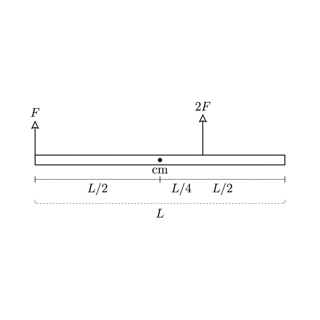
A satellite, modeled as a uniform rod of length LL, is initially at rest. Two thrusters apply constant forces of magnitude FF and 2F2F perpendicular to the rod at the positions shown in the figure.

Question

Which claim correctly describes the angular velocity of the satellite while the thrusters are firing?

It remains constant at zero because the net torque exerted on the satellite is zero.

It increases at a constant rate because the net force exerted on the satellite is 3F3F.

It increases at a constant rate because the force 2F2F is greater in magnitude than the force FF.

It increases at a constant rate because the forces are applied at different distances from the center of mass.

setup_diagram

Stimulus-based practice question

setup_diagram

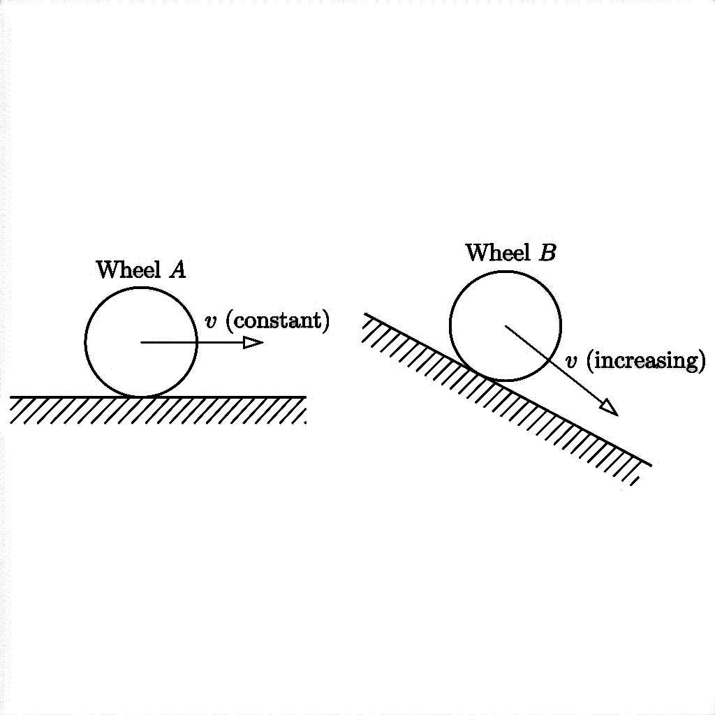
Wheel A rolls without slipping at a constant speed along a horizontal surface. Wheel B rolls without slipping down an inclined plane, increasing in speed as it moves.

Question

How do the magnitudes of the net torques about the center of mass for Wheel A and Wheel B compare, and what does this indicate about their rotational equilibrium?

τA<τB\tau_A < \tau_B; Wheel A is in rotational equilibrium, while Wheel B is not.

τA<τB\tau_A < \tau_B; neither wheel is in rotational equilibrium because both are moving.

τA=τB\tau_A = \tau_B; both wheels are in rotational equilibrium because they roll without slipping.

τA>τB\tau_A > \tau_B; Wheel A requires a greater net torque to maintain a constant speed on a horizontal surface.

Example FRQs

open all FRQs
FRQ

Angular acceleration of rotating disk-pulley system

3. Students are investigating how torque affects the angular acceleration of a rotating system.

Figure 1. Disk-pulley apparatus for angular acceleration

A clean, black-and-white physics apparatus diagram (no 3D perspective; simple line art) showing a rotating disk on a horizontal axle with a rigidly attached pulley and a hanging mass on a string.

Overall layout (left-to-right):
- The rotating disk-and-axle assembly occupies the left half of the figure.
- The string and hanging mass occupy the right half of the figure, with the mass clearly below the pulley.

Disk and axle:
- Draw a large circle representing the disk, centered vertically on the page and placed in the left half.
- Draw a straight horizontal axle passing through the exact center of the disk, extending a short distance to the left and right beyond the disk’s edge.
- Label the disk with the text "disk" placed inside the circle.
- Label the axle with the text "axle" placed just below the horizontal axle line, with a short leader line pointing to the axle.

Pulley (rigidly attached to axle):
- Draw a smaller circle (the pulley) centered on the same point as the disk and coaxial with the axle (i.e., the pulley’s center is exactly the disk’s center).
- The pulley circle must be visibly smaller than the disk (pulley diameter clearly less than half the disk diameter), emphasizing that it is a small pulley attached at the hub.
- Add a radius indicator: draw a straight line from the pulley’s center to the pulley rim pointing up and slightly right (diagonal), and label it "R = 0.0250 m". The label must be immediately next to the radius line.
- Label the pulley with the text "pulley" placed near the small circle, with a leader line pointing to the pulley rim.

String path (no slipping implied):
- Draw a thin line representing the string wrapped around the pulley. The string must contact the pulley rim on the right-hand side.
- From the rightmost point of tangency on the pulley rim, the string leaves the pulley and continues as a perfectly vertical line downward.
- The vertical string segment must be drawn to the right of the disk/pulley so that it is visually separate and unobstructed.
- Label the string with the text "string" placed near the vertical segment, with a short leader line pointing to the string.

Hanging mass:
- At the bottom end of the vertical string, draw a small rectangular mass hanger (or block) attached directly to the string.
- Place the mass entirely in the lower-right quadrant of the figure, directly below the vertical string.
- Label the hanging mass with the text "m" placed next to the rectangle.
- Add a motion arrow: draw a bold arrow immediately to the right of the mass pointing straight downward. Next to the arrow, write "motion" or "down" (choose exactly one; use "down").

Angular acceleration indication:
- Near the rim of the disk, draw a curved arrow indicating rotation. The curved arrow must be centered on the disk and follow the disk’s circular edge.
- Place the curved arrow on the upper-left side of the disk so it does not overlap the string.
- Label this curved arrow with the text "α" placed just outside the disk rim near the arrowhead.

Photogate and marker:
- Draw a small rectangular photogate symbol positioned to the left of the disk rim (not touching the disk), at the same vertical height as the disk center.
- The photogate must appear as a U-shape or rectangular gate opening facing the disk, indicating it detects a passing marker.
- On the disk rim closest to the photogate, draw a small contrasting marker (a short thick line segment or small filled rectangle) on the disk edge.
- Label the photogate with the text "photogate" placed above it, with a leader line pointing to the gate.
- Label the rim marker with the text "marker" placed near the disk rim, with a leader line pointing to the marker.

Text and clarity rules:
- The only numerical value shown anywhere in the diagram is exactly "R = 0.0250 m".
- All labels must be clearly separated (no overlaps) and must point unambiguously to the correct object.
- No extra components (no meter sticks, no additional sensors) beyond disk, axle, pulley, string, mass m, motion arrow, α arrow, photogate, and marker.

Figure 2. Grid for linearized relationship plot

A blank Cartesian coordinate grid intended for student plotting, with BOTH axes drawn as heavy lines with arrowheads and full numeric tick labels. The grid must be large and centered.

Axes and labels (exact visible text):
- Horizontal axis label centered below the axis: "1/m (1/kg)".
- Vertical axis label along the left side, rotated vertically: "(m/s^2) / α".
- Note: The vertical label is written exactly as the fraction text "(m/s^2) / α" (not typeset as a stacked fraction).

Horizontal axis scale (exact):
- Leftmost labeled tick: "0" at the origin.
- Rightmost labeled tick: "25" at the far right end.
- Labeled tick marks every 5 units: 0, 5, 10, 15, 20, 25.
- Minor gridlines (lighter) subdivide each 5-unit interval into five equal parts (i.e., 1-unit spacing), but only the 5-unit ticks carry numbers.

Vertical axis scale (exact):
- Bottom labeled tick: "0" at the origin.
- Top labeled tick: "8" at the top end.
- Labeled tick marks every 1 unit: 0, 1, 2, 3, 4, 5, 6, 7, 8.
- Horizontal gridlines at every 1 unit, with lighter minor styling not needed (keep a single grid spacing of 1 vertically).

Grid appearance:
- Use a standard square grid with evenly spaced vertical and horizontal gridlines.
- The origin is at the bottom-left corner of the grid area.
- No data points, no best-fit line, and no title.
- Keep ample blank margin around the grid so labels are not clipped.

Table 1. Hanging mass and angular acceleration data

A data table titled "Table 1" with exactly 2 columns and exactly 6 rows total (1 header row + 5 data rows). Use clear ruled lines separating all cells.

Column headers (top row, exact text including units):
- Column 1 header: "m (kg)"
- Column 2 header: "α (rad/s^2)"

Data rows (each row contains two entries; keep exactly the shown significant figures as text):
- Row 1: 0.050 | 1.45
- Row 2: 0.070 | 1.96
- Row 3: 0.090 | 2.44
- Row 4: 0.110 | 2.88
- Row 5: 0.130 | 3.33

Formatting requirements:
- Values are centered within their cells.
- Use the Greek letter alpha "α" in the header (not the word 'alpha').
- No extra columns, no extra blank rows, and no additional notes inside the table.
A.

Describe an experimental procedure the students could use to determine the angular acceleration α of the disk when a hanging mass m is released from rest. Include the measurements to be made, how the measurements are used to determine α using angular kinematics, and one method to reduce experimental uncertainty.

B.

The students model the system as follows. The hanging mass m accelerates downward with linear acceleration a while the disk-and-pulley rotate with angular acceleration α. The string does not slip on the pulley, so a = αR. The torque on the rotating system due to the string is τ = TR, where T is the string tension. The net torque about the axle is related to angular acceleration by τ = Iα. Using Newton’s second law for the hanging mass and the relationships above, the students determine that

α = (m g R) / (I + mR^2)

Describe how the students could use measurements of α for different values of m to create a linear graph and how the slope of that graph could be used to determine the rotational inertia I. Clearly identify what quantities are plotted on each axis and how the slope is related to I.

m (kg)

α (rad/s^2)

0.050

1.45

0.070

1.96

0.090

2.44

0.110

2.88

0.130

3.33

C.

The students perform five trials using different hanging masses m. For each trial, the students release the system from rest and measure the time Δt for the disk to rotate through an angular displacement of Δθ = 6.00 rad. The students use rotational kinematics (Δθ = (1/2)α(Δt)^2) to determine α for each trial. The values of m and the calculated α are shown in Table 1.

The students decide to graph 1/m on the horizontal axis.

i.

Indicate what measured or calculated quantity could be plotted on the vertical axis to yield a linear graph whose slope can be used to calculate an experimental value for the rotational inertia I.

Vertical axis: Horizontal axis: 1/m

ii.

On the blank grid provided, create a graph of the quantities indicated in part C(i) that can be used to determine I.

Use Table 2 to record the data points or calculated quantities that you will plot.

Clearly label the vertical axis, including units as appropriate.

Plot the points you recorded in Table 2.

iii.

Draw a straight best-fit line for the data graphed in part C(ii).

D.

Using the best-fit line that you drew in part C(iii), calculate an experimental value for the rotational inertia I of the disk-and-pulley system. Use g = 9.80 m/s^2 and R = 0.0250 m.

FRQ

Angular acceleration of rotating disk systems

4. In Scenario 1, a uniform solid disk of mass M=2.0 kgM = 2.0\ \text{kg} and radius R=0.40 mR = 0.40\ \text{m} can rotate without friction about a fixed horizontal axle through its center. A light string is wrapped around the rim of the disk and is pulled tangentially with a constant force of magnitude F1=6.0 NF_1 = 6.0\ \text{N}, as shown in Figure 1. The disk starts from rest and has an initial angular acceleration of magnitude α1\alpha_1. All frictional forces are negligible, and the string does not slip on the disk.

In Scenario 2, the same disk rotates about the same axle. A light string is wrapped around a smaller radius pulley rigidly attached to the disk so that the string is tangent to a circle of radius r=0.20 mr = 0.20\ \text{m}. The string is pulled tangentially with the same constant force magnitude F2=6.0 NF_2 = 6.0\ \text{N}, as shown in Figure 2. The disk again starts from rest and has an initial angular acceleration of magnitude α2\alpha_2. All frictional forces are negligible, and the string does not slip.

Figure 1. Scenario 1: A constant tangential pull F₁ = 6.0 N applied at the outer rim (radius R = 0.40 m) of a uniform solid disk (mass M = 2.0 kg).

Single-panel black-and-white physics schematic (no perspective; flat front view of the disk).

Overall layout:
- Place a large circle (the disk) centered in the panel, occupying most of the height.
- Draw a small filled dot at the exact center of the circle to mark the axle. Through this central dot, draw a short horizontal line segment (left-to-right) to represent the fixed horizontal axle; the line extends equally on both sides of the disk center.

Disk labeling:
- Inside the disk, near the upper-left interior quadrant, place the text: "M = 2.0 kg".
- Near the right side of the disk, add a radius annotation for the outer rim: draw a straight line from the center dot to the rim at the rightmost point of the disk. Label this line "R = 0.40 m" with the text placed just outside the disk on the right, and the label clearly associated with that center-to-rim line.

String and force application (tangential at the outer rim):
- Show a light string wrapped around only a small arc of the outer rim near the top of the disk (so it is clear the string contacts the rim). The wrapped arc should be visibly on the rim itself.
- From the topmost point of the disk (the 12 o’clock point), draw the string leaving the disk as a perfectly straight horizontal segment extending to the right.
- At the far right end of this straight string segment, draw a simple hand icon grasping the string.
- Along the straight string segment (near the hand, but not overlapping it), draw a bold force arrow pointing directly to the right. Label the arrow with the text exactly: "F₁ = 6.0 N" placed just above the arrow.

Tangency and perpendicularity cues (to enforce exact torque geometry):
- At the exact topmost contact point (12 o’clock), draw a short radius line from the disk center to that topmost rim point (a thin line). This radius line is vertical.
- Ensure the straight string segment is exactly horizontal at the contact point, making it visually perpendicular to the vertical radius line at that point, clearly indicating tangential pull.

Rotation indication:
- Near the outer rim on the left side of the disk, draw a curved arrow centered on the axle indicating the direction of rotation caused by pulling to the right at the top. The curved arrow should indicate clockwise rotation (arrowhead pointing downward on the left side arc, consistent with a rightward tangential force at the top).

Cleanliness/constraints:
- No additional forces are drawn.
- No friction symbols.
- All text is printed clearly and does not overlap lines: "M = 2.0 kg", "R = 0.40 m", and "F₁ = 6.0 N" must be visible.

Figure 2. Scenario 2: The same disk (M = 2.0 kg, R = 0.40 m) with a rigidly attached inner pulley (radius r = 0.20 m) pulled by the same constant tangential force F₂ = 6.0 N.

Single-panel black-and-white physics schematic (no perspective; flat front view), matching the style and disk size of Figure 1.

Overall layout:
- Draw the same large disk as in Figure 1: a circle centered in the panel with a central axle.
- Mark the axle with a small filled center dot. Draw a short horizontal line segment through the dot to represent the fixed horizontal axle.

Disk and pulley geometry:
- Inside the large disk, draw a second, smaller concentric circle (the rigidly attached inner pulley). This inner circle is centered exactly on the same axle dot.
- The inner pulley radius is exactly half the outer disk radius in the drawing (so the inner circle’s radius is drawn as one-half of the outer circle’s radius), reflecting r = 0.20 m and R = 0.40 m.

Labels for mass and radii:
- Inside the large disk, near the upper-left interior quadrant, place the text: "M = 2.0 kg".
- On the right side, draw a radius line from the center dot to the outer rim at the rightmost point of the large disk; label it "R = 0.40 m" with the label placed just outside the outer rim.
- Also on the right side, draw a separate, shorter radius line from the center dot to the rightmost point of the inner pulley circle; label it "r = 0.20 m" with the text placed between the inner and outer circles (or just outside the inner circle) so it is unambiguous that it refers to the inner radius, not the outer radius.

String and force application (tangential at the inner pulley):
- Show a light string wrapped around only a small arc of the inner pulley near its top (the string must clearly touch the inner circle, not the outer rim).
- From the topmost point of the inner pulley (the 12 o’clock point of the inner circle), draw the string leaving as a perfectly straight horizontal segment extending to the right, passing through the space inside the outer disk boundary and then continuing to the right outside the disk.
- At the far right end of the straight string segment, draw a simple hand icon grasping the string.
- Along the straight string segment (near the hand), draw a bold force arrow pointing directly to the right. Label it with the text exactly: "F₂ = 6.0 N" placed just above the arrow.

Tangency and perpendicularity cues (to enforce exact torque geometry at radius r):
- At the exact topmost contact point on the inner pulley, draw a thin vertical radius line from the center dot to that inner-circle top point.
- Ensure the straight string segment is exactly horizontal at the contact point, making it visually perpendicular to that vertical radius line, clearly indicating the force is tangent to the circle of radius r.

Rotation indication:
- Near the left side of the disk (outside the inner pulley but inside the outer rim), draw a curved arrow about the axle indicating clockwise rotation (same direction as Figure 1).

Cleanliness/constraints:
- Do not draw the string contacting the outer rim anywhere; it must only contact the inner pulley arc.
- No additional forces are drawn.
- All text is readable and non-overlapping: "M = 2.0 kg", "R = 0.40 m", "r = 0.20 m", and "F₂ = 6.0 N" must be visible.
A.

Refer to Figure 2. Refer to Figure 1. Indicate whether α1\alpha_1 is greater than, less than, or equal to α2\alpha_2 by writing one of the following in your answer booklet.

α1>α2\alpha_1 > \alpha_2
α1<α2\alpha_1 < \alpha_2
α1=α2\alpha_1 = \alpha_2

Justify your answer in terms of ALL torques exerted on the disk about the axle in each scenario. Use qualitative reasoning beyond referencing equations.

B.

Starting with Newton's second law for rotation, derive an expression for the initial angular acceleration magnitude α\alpha of the disk. Express your answer in terms of FF, dd, MM, RR, and physical constants, as appropriate. Begin your derivation by writing a fundamental physics principle or an equation from the reference information. Consider the general case of the same uniform solid disk (mass MM, radius RR) pulled tangentially by a string with constant force magnitude FF applied at a radius dd from the axle (where 0<dR0<d≤ R). The disk rotates about a fixed axle through its center, and friction is negligible.

C.

Indicate whether the expression for α\alpha you derived in part B is or is not consistent with the claim made in part A. Briefly justify your answer by referencing your derivation in part B.

FRQ

Angular momentum conservation in rotating systems

1. A uniform solid disk of radius 0.20 m and mass 2.0 kg is mounted on a low-friction axle through its center, as shown in Figure 1. A light string is wrapped around the rim of the disk and is pulled by a student with a constant force of 8.0 N, causing the disk to rotate.

Figure 1. Uniform solid disk with tangential force

Black-and-white physics apparatus diagram (no shading), showing a single uniform solid disk viewed face-on (so the disk appears as a perfect circle) with an axle through its center.

Layout and object placement (use relative positioning tied to the frame):
- Place the disk centered horizontally and vertically in the figure so that there is clear empty space above the disk for the string and to the right of the disk for the force arrow and label.
- Draw the disk as a circle with a clearly marked center point.
- Draw the axle as a short horizontal line segment passing through the center point and extending slightly beyond the left and right edges of the disk (the axle line must be straight and exactly through the center).
- Mark the rotation axis at the center with a small solid dot at the circle’s center and a short label pointing to it reading: "axis" (or "axle").

Disk labels (must be visible text on the diagram):
- Near the upper-left of the disk, add a label "R = 0.20 m" with a thin leader line pointing to a radius indicator.
- The radius indicator must be a straight line drawn from the center of the disk to the rim, ending exactly on the circumference. The radius line should point straight upward from the center to the topmost point of the rim (vertical radius).
- Near the lower-left of the disk, add a label "M = 2.0 kg" with no ambiguity that it refers to the disk (place the text adjacent to the disk boundary).

String and force application (must be tangent and at the top):
- At the topmost point of the disk (the point directly above the center), draw a short visible segment of a thin string that touches the rim exactly at that topmost point.
- From that contact point, extend the string horizontally to the right as a straight line (string must be perfectly horizontal).
- At the far right end of the visible string, draw a force arrow pointing to the right, collinear with the string.
- Label the force arrow directly above it with the exact text "F = 8.0 N".
- Ensure the force arrow is drawn as a single straight arrow (not curved), and that it is tangent to the disk at the topmost rim point (the arrow must not point radially; it must be horizontal).

Rotation direction indicator:
- On the right half of the disk face, draw a curved arrow that follows the disk’s circumference direction to indicate counterclockwise rotation.
- The curved arrow must wrap in the counterclockwise sense: its arrowhead should point upward on the right side of the disk (showing motion from the bottom-right toward the top-right along the rim).
- Place the curved arrow entirely inside the disk boundary so it does not overlap the string.

Clarity constraints:
- Only one disk is shown.
- No additional forces or friction arrows.
- All text shown must be exactly: "R = 0.20 m", "M = 2.0 kg", and "F = 8.0 N", plus the small "axis" (or "axle") label.
- The string must contact the rim at exactly the topmost point; the force arrow must be exactly horizontal to the right.

Figure 2. Axes for angular velocity vs. time

A blank Cartesian graph with only axes, tick marks, tick labels, and optional light grid lines (no plotted curve).

Axes and ranges (must be numerically explicit):
- Horizontal axis: labeled "t (s)" centered below the axis.
  - Range: from 0 at the origin to 3.0 at the right end.
  - Tick marks and labels: show tick labels exactly at 0, 1.5, and 3.0.
  - The tick at 1.5 must be visually between 0 and 3.0 exactly halfway along the horizontal axis.
- Vertical axis: labeled "ω (rad/s)" centered along the vertical axis.
  - Range: from 0 at the origin to 90 at the top end.
  - Tick marks and labels: show evenly spaced tick labels at 0, 30, 60, and 90.
- The origin must be labeled "0" at the intersection of the axes.
- Add arrowheads on the positive (rightward) end of the t-axis and on the positive (upward) end of the ω-axis.

Grid specification (to match the original intent of grid lines without ambiguity):
- Include faint, evenly spaced grid lines.
- Vertical grid lines: align with the labeled x-ticks at 0, 1.5, and 3.0 (major grid lines).
- Horizontal grid lines: align with the labeled y-ticks at 0, 30, 60, and 90 (major grid lines).

Blank-graph constraints:
- Do not draw any curve, points, arrows on the graph area, or annotations besides axis labels and tick labels.
- No title text inside the plot area.
A.
i.

On the axes shown in Figure 2, sketch a graph of the disk’s angular velocity ω as a function of time t from t = 0 to t = 3.0 s.

ii.

Derive an expression for the magnitude of the angular acceleration α of the disk during the time interval from t = 0 to t = 1.5 s in terms of the given quantities and physical constants, as appropriate. Begin your derivation by writing a fundamental physics principle or an equation from the reference information.

iii.

Derive an expression for the magnitude of the linear speed v of a point on the rim of the disk at t = 1.5 s in terms of the given quantities and physical constants, as appropriate. Begin your derivation by writing a fundamental physics principle or an equation from the reference information.

B.

Indicate whether the angular speed of the disk-plus-point-mass system at t = 1.5 s is greater than, less than, or equal to the angular speed of the disk alone at t = 1.5 s. The same student repeats the experiment, but now a point mass of 0.50 kg is attached to the disk at the rim (0.20 m from the axle). The student again pulls with the same constant force of 8.0 N, tangent to the rim, for the same time interval from t = 0 to t = 1.5 s. The disk again starts from rest, and frictional torques remain negligible.

Greater than
Less than
Equal to
Justify your response.

Key terms

TermDefinition
axis of rotationThe specified line about which a rigid system rotates; the reference point for measuring torque, lever arm, and rotational inertia.
rigid systemA system that holds its shape during rotation, with all points sharing the same angular velocity and angular acceleration even though they travel different linear distances.
constant angular accelerationA condition in which angular velocity changes at a uniform rate, allowing the use of rotational kinematic equations analogous to constant linear acceleration equations from Unit 1.
Δs = r ΔθThe arc length a point travels equals its distance from the axis times the angular displacement in radians; the foundation for v = rω and a_T = rα.
lever armThe perpendicular distance from the axis of rotation to the line of action of an applied force; a longer lever arm produces greater torque for the same force magnitude.
moment armThe perpendicular distance from the axis of rotation to the line of action of a force, used interchangeably with lever arm to calculate torque as τ = rF sinθ.
force diagramA diagram similar to a free-body diagram used to analyze torques on a rigid system, showing force magnitudes, directions, and points of application relative to the axis of rotation.
parallel axis theoremI' = I_cm + Md²; gives the rotational inertia about any axis parallel to one through the center of mass, where d is the perpendicular distance between the two axes. Rotational inertia is minimum when the axis passes through the center of mass.

Common unit 5 mistakes

Using degrees instead of radians

All rotational kinematic equations and the arc length formula s = rθ require θ in radians. Converting to degrees before calculating will give wrong answers. Always check your units before substituting.

Using the full force instead of the perpendicular component for torque

Only the component of force perpendicular to the position vector from the axis causes rotation. If a force is applied at an angle, you must use τ = rF sinθ, not τ = rF. Forgetting the sinθ factor is one of the most common torque errors.

Treating rotational inertia like mass in torque problems

Rotational inertia depends on both mass and the square of the distance from the axis. Doubling the distance from the axis quadruples I, not doubles it. Always square the radius when calculating I = mr².

Assuming rotational and translational equilibrium always occur together

A system can have zero net torque (constant ω) while its center of mass accelerates, or zero net force (constant v_cm) while angular velocity changes. These conditions are independent and must be checked separately.

Forgetting to connect linear and rotational analyses with a = rα

In problems with a hanging mass and a pulley, students often write separate equations but forget to use a = rα to link the linear acceleration of the mass to the angular acceleration of the pulley. Without this constraint, the system is underdetermined.

How this unit shows up on the AP exam

Functional dependence and proportional reasoning

The AP Physics 1 exam frequently asks how angular acceleration changes when net torque or rotational inertia changes by a given factor. You should be able to use α = τ_net / I to explain, without numbers, that doubling I halves α for the same torque, or that tripling τ_net triples α for the same I. Written justification of these proportional relationships is a core skill tested in both multiple-choice and free-response questions.

Combined linear and rotational system analysis

Free-response questions in this unit often involve systems where a hanging mass drives a rotating pulley or a force causes both translation and rotation. You are expected to write separate Newton's second law equations for the linear and rotational components, then connect them using the constraint a = rα. Clearly labeling which equation applies to which part of the system and showing the connection step is essential for full credit.

Rotational equilibrium and torque balance problems

Questions may present a beam, rod, or lever with multiple forces and ask you to find an unknown force or distance that maintains rotational equilibrium. The skill is setting up Στ = 0 about a strategically chosen pivot, correctly computing each torque with its sign, and solving algebraically. You may also need to explain why a system is or is not in rotational equilibrium based on a described or diagrammed scenario.

Final unit 5 review checklist

  • Unit 5 final review checklistUse this checklist to confirm you can handle every major skill in Unit 5 before your exam.
  • Apply rotational kinematic equationsGiven initial angular velocity, angular acceleration, and time (or angular displacement), solve for any unknown using ω = ω₀ + αt and θ = θ₀ + ω₀t + ½αt². Confirm you are working in radians.
  • Convert between linear and angular quantitiesUse s = rθ, v = rω, and a_T = rα to find the linear motion of any point on a rotating rigid system given its distance from the axis and the system's angular quantities.
  • Calculate torque from a force diagramIdentify the axis, find the lever arm or use τ = rF sinθ, assign correct signs for clockwise and counterclockwise torques, and sum all torques on the system.
  • Determine rotational inertia for discrete systemsApply I = mr² to each point mass and sum them. Use the parallel axis theorem I' = I_cm + Md² when the axis is not through the center of mass. Qualitatively explain why mass farther from the axis increases I.
  • Set up and solve rotational equilibrium problemsApply Στ = 0, choose a pivot that eliminates an unknown force, and solve for the remaining unknowns. Distinguish rotational equilibrium from translational equilibrium.
  • Apply Newton's second law in rotational formUse α = τ_net / I to find angular acceleration. For combined systems (block and pulley), write separate equations for linear and rotational motion and connect them with a = rα.
  • Explain functional dependence relationshipsDescribe how α changes when τ_net or I changes by a given factor, and justify the reasoning using α = τ_net / I without plugging in numbers.

How to study unit 5

Step 1: Build rotational kinematics fluency (5.1 and 5.2)Read the topic guides for 5.1 and 5.2. Practice converting between angular and linear quantities using s = rθ, v = rω, and a_T = rα. Solve several constant-angular-acceleration problems using the rotational kinematic equations, confirming you work in radians throughout.
Step 2: Understand torque calculation and force diagrams (5.3)Read the topic guide for 5.3. Draw force diagrams for at least three different scenarios, identifying the axis, the lever arm, and the perpendicular force component. Practice calculating τ = rF sinθ for forces applied at various angles, and assign correct signs for clockwise and counterclockwise torques.
Step 3: Calculate and compare rotational inertia (5.4)Read the topic guide for 5.4. Practice computing I_total = Σmᵢrᵢ² for systems of two to five point masses. Apply the parallel axis theorem to shift the axis off-center. Qualitatively compare rotational inertia for hoops versus disks and rods about different axes.
Step 4: Solve rotational equilibrium problems (5.5)Read the topic guide for 5.5. Set up Στ = 0 for balance problems, choosing pivot points strategically to eliminate unknown forces. Practice distinguishing scenarios that are in rotational equilibrium but not translational equilibrium, and vice versa.
Step 5: Apply Newton's second law in rotational form and combine analyses (5.6)Read the topic guide for 5.6. Solve problems using α = τ_net / I, including functional dependence questions where you explain how α changes when τ or I changes by a factor. Practice combined block-and-pulley problems by writing separate linear and rotational equations and connecting them with a = rα. Use the AP score calculator to estimate your overall score as you work through practice questions.

More ways to review

Topic study guides

Open the individual guides for Unit 5 when you want a closer review of one topic.

browse guides

Practice questions

Use AP-style practice after you review the notes so you can check what you understand.

start practice

FRQ practice

Practice free-response reasoning and compare your answer with scoring guidance.

practice FRQs

Cheatsheets

Use unit cheatsheets for a quick visual review after you work through the notes.

open cheatsheets

Score calculator

Estimate your broader AP score goal after you review the course and exam format.

open calculator

Frequently Asked Questions

What topics are covered in AP Physics 1 Unit 5?

AP Physics 1 Unit 5 covers 6 topics in torque and rotational dynamics: Rotational Kinematics (5.1), Connecting Linear and Rotational Motion (5.2), Torque (5.3), Rotational Inertia (5.4), Rotational Equilibrium and Newton's First Law in Rotational Form (5.5), and Newton's Second Law in Rotational Form (5.6). These topics build directly on linear motion and force concepts, translating them into their rotational equivalents. By the end of the unit, you can analyze systems that combine both linear and rotational motion. See all six topics at /ap-physics-1-revised/unit-5.

How much of the AP Physics 1 exam is Unit 5?

AP Physics 1 Unit 5 makes up 10-15% of the AP exam, making torque and rotational dynamics one of the more heavily tested concept areas. That means you can expect a meaningful number of multiple-choice questions and potentially an FRQ touching on topics like rotational inertia, Newton's Second Law in rotational form, and rotational equilibrium. Given that weight, it's worth spending solid time here, especially on connecting rotational kinematics to the linear motion concepts you already know.

What's on the AP Physics 1 Unit 5 progress check (MCQ and FRQ)?

The AP Physics 1 Unit 5 progress check in AP Classroom includes both MCQ and FRQ parts drawn from all six unit topics: rotational kinematics, connecting linear and rotational motion, torque, rotational inertia, rotational equilibrium, and Newton's Second Law in rotational form. The MCQ section tests conceptual understanding and quantitative reasoning across these topics, while the FRQ part typically asks you to apply Newton's laws in rotational form or analyze a system in rotational equilibrium. For matched practice that mirrors the progress check format, check out /ap-physics-1-revised/unit-5.

How do I practice AP Physics 1 Unit 5 FRQs?

AP Physics 1 Unit 5 FRQs most often focus on torque, rotational inertia, and Newton's Second Law in rotational form, asking you to set up equations, justify reasoning, or analyze a physical scenario involving rotational equilibrium. To practice effectively, work through problems where you draw extended free-body diagrams, identify the pivot point, and write out net torque equations step by step. Good habits: always define your sign convention for rotation, show your algebra clearly, and connect back to the physical situation in your explanation. You can find FRQ-style practice problems at /ap-physics-1-revised/unit-5.

Where can I find AP Physics 1 Unit 5 practice questions?

The best place to find AP Physics 1 Unit 5 practice questions, including multiple-choice and practice test problems on torque and rotational dynamics, is /ap-physics-1-revised/unit-5. There you'll find MCQ practice covering all six topics, from rotational kinematics and rotational inertia to rotational equilibrium and Newton's Second Law in rotational form. For the most targeted prep, focus your MCQ practice on problems that ask you to compare rotational inertia for different mass distributions and apply torque to find angular acceleration.

How should I study AP Physics 1 Unit 5?

Start AP Physics 1 Unit 5 by locking in rotational kinematics (5.1) and the connections to linear motion (5.2), since those relationships, like angular velocity linking to linear velocity, show up throughout the rest of the unit. Then build toward torque and rotational inertia before tackling Newton's laws in rotational form. Here's a concrete study sequence: 1. Review rotational kinematics equations alongside their linear counterparts so the patterns stick. 2. Practice drawing extended free-body diagrams to identify torques and pivot points. 3. Work problems on rotational inertia for different object shapes, since the mass distribution matters. 4. Apply Newton's Second Law in rotational form to systems with multiple torques. 5. Test yourself with mixed MCQ and FRQ practice at /ap-physics-1-revised/unit-5. Since this unit is 10-15% of the exam, even a few focused study sessions here can meaningfully move your score.

Ready to review Unit 5?Start with the notes, check the topic cards, and use the practice or resource links when they are available for this course.