Coordinate systems and transformations give robots a way to describe where things are in space and how to move between different positions. Without them, a robot has no consistent language for locating itself, its tools, or the objects it needs to interact with. This guide covers the main coordinate systems, how transformations work (and how to represent them with matrices), rotation representations like Euler angles and quaternions, and the basics of forward and inverse kinematics.
Types of coordinate systems
Coordinate systems give you a standardized way to pin down the position and orientation of objects in space. Different systems fit different situations, and robots often need to convert between them depending on the geometry of the task.
Cartesian coordinate system
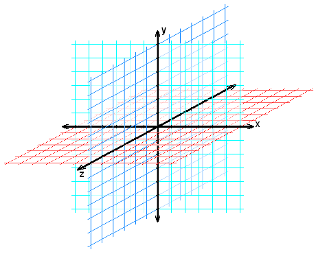
The Cartesian system represents points using three perpendicular axes: x, y, and z. Each point is specified as , representing distances from the origin along each axis.
This is the most common system in robotics, computer graphics, and CAD because it's intuitive and maps directly to how we think about left/right, forward/back, and up/down. Applications like 3D printing and CNC machining rely heavily on Cartesian coordinates. That said, Cartesian coordinates can be awkward for problems involving circular or spherical geometry.
Polar coordinate system
Polar coordinates describe a point in a 2D plane using:
- : the distance from the origin (radius)
- : the angle from a reference direction (polar angle)
A point is written as . This system shines when you're dealing with circular or radial symmetry. Radar systems, for example, naturally produce data in polar form (a distance and a bearing). Calculations like finding the distance between two points on a circle or describing angular relationships become much simpler in polar coordinates compared to Cartesian.
Cylindrical coordinate system
Cylindrical coordinates combine polar coordinates in the xy-plane with a height along the z-axis. A point is specified as .
Think of it as "polar coordinates plus height." This system is a natural fit for problems with axial symmetry, like describing the workspace of a cylindrical robot or modeling screw threads. Rotations around the z-axis and vertical translations are particularly clean in this system.
Spherical coordinate system
Spherical coordinates describe a point in 3D space using:
- : distance from the origin
- : azimuth angle (in the xy-plane)
- : elevation angle (measured from the z-axis)
A point is written as . This system is ideal for problems with spherical symmetry. GPS and celestial navigation both use spherical-style coordinates. Calculations involving distances on a sphere or angular relationships between directions simplify considerably in this system.
Homogeneous coordinates
Homogeneous coordinates extend regular Cartesian coordinates by adding a fourth component, . This seemingly small addition is what makes it possible to represent translation, rotation, scaling, and other transformations all as matrix multiplications.
Representing points and vectors
- A point in homogeneous coordinates is written as . The signals that this is a position in space.
- A vector is written as . Setting means the vector has direction and magnitude but no fixed position, so translation won't affect it.
- To convert back to Cartesian coordinates, divide , , and by (as long as ).
Advantages of homogeneous coordinates
- They let you represent points at infinity (ideal points) by setting .
- All common geometric transformations (translation, rotation, scaling, projection) can be expressed as 4×4 matrix multiplications.
- Composing multiple transformations is just multiplying their matrices together, which keeps things clean and efficient.
- Points and vectors live in the same coordinate system, so you can handle both with the same math.
Coordinate transformations
Coordinate transformations are operations that map points from one coordinate system to another. They're how a robot relates what its camera sees to where its arm needs to move. The most common types are translation, rotation, scaling, and shearing.
Translation
Translation shifts every point by a fixed displacement along each axis. In homogeneous coordinates:
The translation matrix is:

Rotation
Rotation turns an object around a specified axis by an angle . Each axis has its own rotation matrix:
Rotation around the x-axis:
Rotation around the y-axis:
Rotation around the z-axis:
Scaling
Scaling changes the size of an object by factors along each axis:
If all three factors are equal, it's uniform scaling. If they differ, it's non-uniform scaling, which stretches or compresses the object differently along each axis.
Shearing
Shearing distorts an object by shifting points along one axis in proportion to their position along another axis. For example, shearing along the x-axis shifts x-coordinates based on y-values:
Similar matrices exist for shearing along the y-axis and z-axis. Shearing is less common in robotics than translation and rotation, but it shows up in certain deformation and projection tasks.
Transformation matrices
Transformation matrices encode transformations as 4×4 matrices that operate on homogeneous coordinates. Their real power is composability: you can chain multiple transformations together by multiplying their matrices.
Composition of transformations
To apply a sequence of transformations to a point , you multiply the matrices in reverse order:
The rightmost matrix is applied first. Order matters because matrix multiplication is not commutative. Rotating then translating gives a different result than translating then rotating. This is one of the most common sources of bugs when programming robot movements.
Inverse of transformation matrices
The inverse of a transformation matrix undoes the transformation, mapping transformed points back to their original positions. If is a transformation matrix, then (the identity matrix).
- Rotation matrices are orthogonal, so their inverse is simply their transpose: .
- Translation matrices are inverted by negating the translation vector.
- Scaling matrices are inverted by taking the reciprocal of each scaling factor ().
- Shearing matrices have more complex inverses involving the shearing factors.
Inverses are useful for reversing transformations and for figuring out the original coordinates of a point after it's been transformed.
Euler angles
Euler angles describe the orientation of a rigid body using three rotation angles applied in sequence around the coordinate axes. They're intuitive and widely used, but they come with a significant limitation.
Roll, pitch, and yaw
- Roll (): Rotation around the x-axis (tilting side-to-side)
- Pitch (): Rotation around the y-axis (tilting forward/backward)
- Yaw (): Rotation around the z-axis (turning left/right)
The order you apply these rotations changes the final result, since rotations are not commutative. Multiple conventions exist (x-y-z, z-y-x, intrinsic vs. extrinsic), so always check which convention a system uses before plugging in values.
Gimbal lock problem
Gimbal lock is a singularity that occurs when two of the three rotation axes align, collapsing three degrees of freedom into two. This happens when the pitch angle reaches , causing the roll and yaw axes to become parallel.
At that point, changing roll and changing yaw produce the same physical rotation, so you lose the ability to independently control all three axes. This is a real problem for any system that needs smooth, continuous rotation control. Quaternions are the standard solution.
Quaternions
Quaternions are four-component numbers that represent rotations without the singularity problems of Euler angles. A quaternion is written as:
where is the scalar part and is the vector part. The symbols , , and are imaginary units (similar to in complex numbers, but extended to three dimensions).
Representation of rotations
A rotation by angle around a unit axis is represented as:
Notice the half-angle: a 90° rotation uses and , not and . This half-angle formulation is what gives quaternions their nice mathematical properties.
- Quaternions must be unit quaternions (magnitude = 1) to represent valid rotations.
- Composing two rotations is done by multiplying their quaternions. Like matrix multiplication, quaternion multiplication is not commutative.
Advantages over Euler angles
- No gimbal lock. Quaternions don't have singularities.
- Smooth interpolation. Spherical linear interpolation (SLERP) between two quaternions produces a smooth, constant-speed rotation path. This is much harder with Euler angles.
- Numerical stability. Quaternions accumulate less floating-point error over repeated operations.
- Easy conversion. You can convert between quaternions and rotation matrices in both directions.
Quaternions are the standard rotation representation in game engines, VR systems, and many robotics frameworks.
Forward vs inverse kinematics
Kinematics studies the motion of objects without worrying about the forces involved. In robotics, it's specifically about the relationship between a robot arm's joint angles and the position and orientation of its end-effector (the tool or gripper at the tip of the arm).
Forward kinematics
Forward kinematics (FK) answers the question: Given all the joint angles, where is the end-effector?
You start at the robot's base frame and apply a chain of coordinate transformations (one per joint), using the known joint angles and link lengths, until you reach the end-effector frame. FK always has a unique solution because a specific set of joint angles produces exactly one end-effector pose.
FK is used for visualization, simulation, and collision detection.
Inverse kinematics
Inverse kinematics (IK) answers the opposite question: Given a desired end-effector position and orientation, what joint angles achieve it?
This is a much harder problem. You're solving a system of nonlinear equations, and the solution may not be unique:
- Redundant robots (more joints than needed) can have infinitely many solutions.
- Unreachable poses (outside the workspace) have no solution.
- Even for reachable poses, there are often multiple valid joint configurations (think of how your elbow can be "up" or "down" while your hand stays in the same place).
IK is used for motion planning, trajectory generation, and task-level control.
Applications in robotics
Forward and inverse kinematics are foundational across robotics:
- Industrial robotics: Welding, painting, assembly, pick-and-place
- Medical robotics: Surgical assistance, rehabilitation devices, prosthetics
- Service robotics: Household tasks, personal assistance
- Space robotics: Spacecraft maintenance, planetary exploration
Efficient and accurate FK/IK solutions directly affect a robot's performance, precision, and safety.
Coordinate frames in robotics
Coordinate frames are local reference systems attached to different parts of a robot or its environment. Every link, joint, sensor, and tool can have its own frame, and transformations between frames are how the robot relates information from one part of the system to another.
Base frame
The base frame (or world frame) is a fixed reference frame, usually attached to the robot's base or a stable point in the environment. It serves as the global coordinate system. All other frames are described relative to the base frame through chains of transformations.
End-effector frame
The end-effector frame (or tool frame) is attached to the robot's tool or gripper. It describes where the tool is and how it's oriented. When you command a robot to move its tool to a specific pose, you're specifying a desired end-effector frame relative to the base frame. The chain of transformations from base frame to end-effector frame is exactly what forward kinematics computes.