Analog-to-Digital Conversion Fundamentals
Analog-to-digital conversion is the bridge between the continuous analog world of physiological sensors and the discrete digital world of computers. Every time a biomedical system records an ECG, EEG, or pulse oximetry signal, an ADC is doing the work of turning a voltage waveform into numbers a processor can store, analyze, and display.
The quality of that conversion depends on three tightly linked factors: resolution, sampling rate, and accuracy. Understanding how these interact is essential for choosing or designing a data acquisition system that faithfully captures the signal you care about.
ADC Basics
An analog-to-digital converter (ADC) takes a continuous analog voltage and outputs a discrete digital code representing that voltage. It sits between the analog front-end (amplifiers, filters, sensors) and the digital back-end (microcontroller, DSP, or PC).
The conversion process has two core steps:
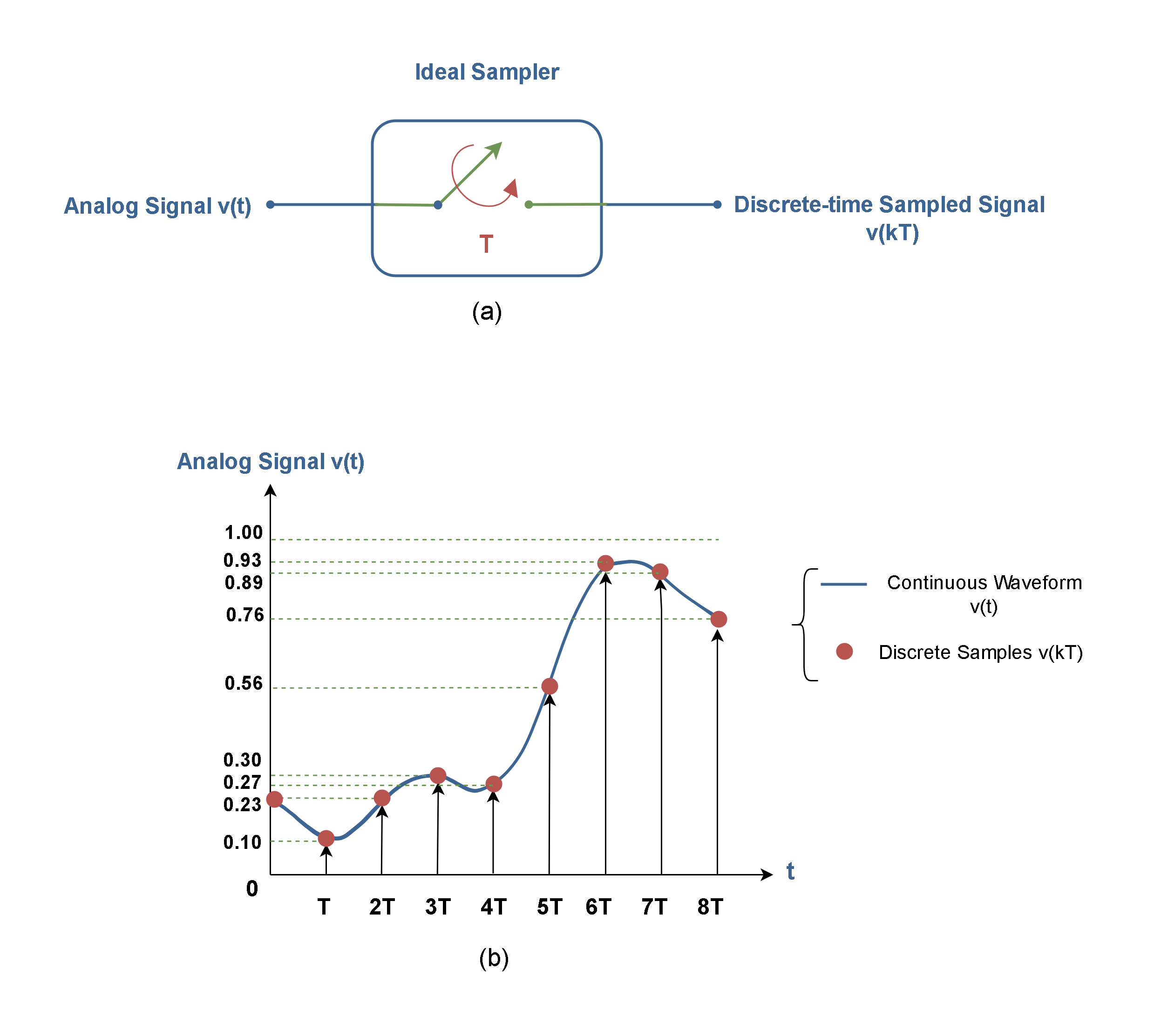
- Sampling — measuring the analog signal at specific time intervals.
- Quantization — rounding each measured value to the nearest discrete level the ADC can represent.
Both steps introduce limitations. Sampling limits how fast a signal can change and still be captured. Quantization limits how precisely each sample reflects the true voltage.
Quantization and Resolution
Quantization maps a continuous range of voltages to a finite set of discrete digital codes. Because the analog value almost never lands exactly on a quantization level, there's always a small rounding error.
Resolution is the number of bits the ADC uses to represent each sample. More bits means more quantization levels and finer voltage distinctions:
- An 8-bit ADC produces levels
- A 12-bit ADC produces levels
- A 16-bit ADC produces levels
The step size (also called the least significant bit voltage, or LSB) is:
where is the full-scale voltage range and is the number of bits. For a 12-bit ADC with a 0–3.3 V range, the step size is about . Any voltage change smaller than that is invisible to the converter.
Quantization error ranges from LSB to LSB. Doubling the resolution (adding one bit) cuts this error in half. For biomedical signals with very small amplitudes (like EEG at ~50 µV), high resolution is critical so the signal isn't buried in quantization noise.

Conversion Error and Accuracy
Quantization error is only one source of inaccuracy. The total conversion error between the true analog value and the digital output also includes:
- Offset error — a constant shift of the entire transfer function away from the ideal.
- Gain error — the slope of the transfer function deviating from ideal, causing errors that grow with signal amplitude.
- Non-linearity — deviations from a straight-line transfer characteristic. This is split into differential non-linearity (DNL), which is variation in individual step sizes, and integral non-linearity (INL), which is cumulative deviation from the ideal line.
- Noise — thermal and electronic noise in the ADC circuitry that causes the output to fluctuate even with a steady input.
Accuracy describes how close the digital output is to the true analog value, accounting for all these errors. It's often specified as ±LSBs or as a percentage of full-scale range.
Two practical techniques for improving effective accuracy:
- Oversampling — sampling at a rate much higher than needed, then averaging. Each 4× increase in oversampling rate gains roughly 1 extra effective bit of resolution.
- Dithering — adding a small amount of noise before conversion to randomize quantization error, which can then be averaged out.
Sampling and Encoding
Sampling Process
Sampling converts a continuous-time signal into a sequence of discrete-time values. The sampling rate () is how many times per second the ADC measures the analog input.
The Nyquist-Shannon sampling theorem sets the minimum requirement:
where is the highest frequency component present in the signal. This minimum rate () is called the Nyquist rate.
If you sample below the Nyquist rate, aliasing occurs. Aliasing folds high-frequency components down into lower frequencies, creating artifacts that are impossible to remove after digitization. A 60 Hz noise component sampled at 100 Hz, for example, would alias to 40 Hz and could be mistaken for a real physiological signal.
To prevent aliasing, an anti-aliasing filter (a low-pass analog filter) is placed before the ADC. It attenuates frequencies above so they can't corrupt the digitized data. In practice, biomedical systems often sample well above the Nyquist rate (typically 5–10× the highest frequency of interest) to give the anti-aliasing filter a more gradual rolloff requirement.
Discrete-Time Signals and Binary Encoding
After sampling and quantization, each value is encoded as a binary word whose length equals the ADC's resolution. Common encoding schemes include:
- Straight (unsigned) binary — used when the input range is unipolar (e.g., 0 to +3.3 V). Code represents the minimum, represents the maximum.
- Two's complement — the standard for representing signed (bipolar) values. The most significant bit indicates the sign, and the remaining bits represent magnitude. This is the most common format in digital signal processing.
- Offset binary — similar to straight binary but shifted so that the midpoint code represents zero. Sometimes used in older ADC hardware.
The encoded binary values are then stored in memory, passed to a microcontroller, or transmitted to a host computer for further processing and display.
Conversion Time and Throughput
Conversion time is how long the ADC takes to produce one digital output from the moment it begins a conversion. Throughput is the maximum number of conversions per second, typically stated in samples per second (SPS).
Different ADC architectures trade off speed, resolution, and complexity:
| Architecture | Typical Speed | Typical Resolution | Common Biomedical Use |
|---|---|---|---|
| Flash | Very fast (>1 GSPS possible) | Low–moderate (6–12 bits) | Ultrasound imaging |
| SAR (Successive Approximation) | Moderate–fast (10 kSPS–5 MSPS) | Moderate–high (10–18 bits) | ECG, EMG, general-purpose DAQ |
| Sigma-Delta (ΣΔ) | Slow–moderate (10 SPS–1 MSPS) | High–very high (16–24 bits) | EEG, precision measurements |
- Flash ADCs use one comparator per quantization level, so an -bit flash ADC needs comparators. Extremely fast, but hardware cost and power scale exponentially with resolution.
- SAR ADCs perform a binary search, testing one bit per clock cycle from MSB to LSB. They offer a good balance of speed and resolution, making them the workhorse of many biomedical data acquisition systems.
- Sigma-Delta ADCs oversample at very high rates and use digital filtering to achieve high resolution with excellent noise rejection. Their slower throughput is acceptable for low-bandwidth signals like EEG (which only extends to ~100 Hz).
Choosing the right architecture depends on the signal: a 24-bit sigma-delta ADC is ideal for capturing tiny EEG voltages at low bandwidth, while a fast SAR or flash ADC is better suited for high-frequency ultrasound echo data.