Centroids are the geometric centers of shapes and objects. In statics and strength of materials, knowing where the centroid is located lets you predict how a structure will respond to loads, where bending stresses concentrate, and whether a design will be stable. This section covers how to find centroids of lines, areas, and volumes using integration, how symmetry shortcuts the process, and how to handle composite shapes.
Centroids via Integration
Centroid Definition and Formulas
The centroid is the average position of all points within a shape or object. Think of it as the "balance point" of pure geometry (no weight or density involved yet).
The general idea is the same across lines, areas, and volumes: you take a weighted average of position, where the "weight" is the differential element (, , or ).
For a line (1D):
where is the total arc length. If the line curves through 2D or 3D space, you'll also need (and possibly ) using the same pattern.
For an area (2D):
where is the total area.
For a volume (3D):
where is the total volume.
Integration Techniques and Considerations
Setting up the integral correctly is usually the hardest part. Here's a practical approach:
- Sketch the shape and choose a coordinate system. Place axes to take advantage of any symmetry.
- Select your differential element. For areas, decide whether to use a vertical strip (), a horizontal strip (), or a thin ring/disk for shapes with radial symmetry.
- Identify the integration limits from the geometry of the shape (where the boundary curves intersect, or where the shape starts and ends along your chosen axis).
- Write and for the element. This is the centroid location of the differential element itself. For a vertical strip of height , the element's centroid is at , not at . This is a common mistake.
- Evaluate the integrals. Use substitution, integration by parts, or other techniques as needed.
For volumes with complex geometry, you may need double or triple integrals. However, many textbook problems can be reduced to single integrals by choosing a smart differential element (thin disks, shells, etc.).
Symmetry in Centroid Calculations
Applying Symmetry to Simplify Calculations
Symmetry is the single biggest time-saver in centroid problems. The core rule is straightforward: if a shape is symmetric about an axis, the centroid lies on that axis.
- One axis of symmetry: The centroid coordinate perpendicular to that axis equals the axis value. For example, if a shape is symmetric about the -axis, then (assuming the -axis is at ). You only need to integrate for .
- Two axes of symmetry: The centroid sits at the intersection of those axes. No integration needed at all for a shape like a rectangle or ellipse centered at the origin.
- Rotational symmetry: Shapes like circles, spheres, and regular polygons have their centroid at the center of rotation.
Recognizing symmetry before you start integrating can cut your work in half (or eliminate it entirely).
Examples of Symmetry in Centroid Calculations
- A rectangle centered at the origin is symmetric about both axes, so its centroid is at the intersection of its diagonals. No integration required.
- A semicircle of radius with its diameter along the -axis is symmetric about the -axis, so . You still need to integrate for , which works out to .
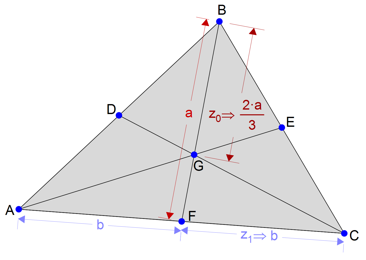
- An equilateral triangle with a vertical line of symmetry has . The centroid sits at one-third of the height measured from the base.
- A sphere is symmetric about all three coordinate axes, so its centroid is at the geometric center.
Centroid Significance in Engineering

Centroid as the Balance Point
For a body with uniform density, the centroid coincides with the center of gravity. That means it's the point where you could support the object and it would balance perfectly without tilting. This connection between geometry and physical behavior is why centroids show up constantly in engineering analysis.
Centroid Applications in Different Engineering Fields
- Structural engineering: The centroid of a beam's cross-section is the reference point for calculating the moment of inertia and bending stress distribution. An I-beam's cross-sectional centroid determines its neutral axis under bending.
- Fluid mechanics: The centroid of a submerged surface determines where the resultant hydrostatic pressure force acts. For submerged objects, it's also tied to where buoyant forces are applied.
- Mechanical engineering: Locating the centroid of rotating components (gears, flywheels) is essential for minimizing vibrations and ensuring proper balance.
- Aerospace engineering: The centroid of wing cross-sections and fuselage sections directly affects aircraft stability and control characteristics.
Centroids for Composite Shapes
Calculating Centroids of Composite Shapes and Solids
Most real engineering cross-sections aren't simple rectangles or circles. They're composite shapes built from several simpler pieces. Instead of integrating over the entire complex shape, you use a weighted-average approach.
The method works in clear steps:
- Decompose the composite shape into simple parts whose individual centroids you already know (rectangles, triangles, semicircles, etc.).
- Tabulate the area (or volume) and centroid coordinates of each part. A table with columns for , , , , and keeps things organized.
- Apply the weighted average formulas:
For composite areas:
For composite volumes:
Combining and Subtracting Shapes or Solids
Holes and cutouts are handled by treating the removed material as a component with negative area or volume. This is one of the most useful tricks in composite centroid problems.
For example, to find the centroid of a plate with a circular hole:
- Treat the full plate (no hole) as component 1 with positive area .
- Treat the hole as component 2 with negative area .
- Plug both into the weighted average formula. The negative area automatically shifts the centroid away from the hole.
Common composite shapes you'll encounter include:
- I-beams: three rectangles (two flanges + one web)
- T-sections: two rectangles
- Channel sections: rectangles with subtracted regions
- Complex cross-sections: combinations of standard shapes with cutouts
The key to getting these right is being careful with your coordinate system. Pick a single reference origin and measure every component's centroid from that same point. Mixing up reference points is the most common source of errors in composite centroid problems.