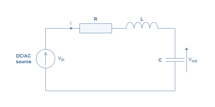
Resonance in AC circuits occurs when inductive and capacitive reactances cancel out. This phenomenon leads to maximum current amplitude and zero phase angle between voltage and current, making the circuit behave purely resistively.
The resonant frequency, quality factor, and bandwidth are key concepts in understanding resonance. These parameters determine circuit selectivity and performance in applications like filters, oscillators, and tuning circuits.
Resonance in AC Circuits
Resonant frequency calculation
- Resonant frequency () occurs when impedance of RLC circuit becomes purely resistive
- Inductive reactance () and capacitive reactance () cancel out at resonance due to equal magnitude but opposite signs
- Calculate resonant frequency using formula
- represents inductance measured in henries (H)
- represents capacitance measured in farads (F)
- Angular resonant frequency () relates to resonant frequency by
- Useful for calculating quality factor and bandwidth
Current changes at resonance
- Current amplitude reaches maximum value at resonance
- Total impedance minimizes, equaling resistance () in circuit
- Calculate current amplitude at resonance using , where represents applied voltage amplitude
- Phase angle between applied voltage and current becomes zero at resonance
- Voltage and current align in phase with each other
- Circuit behaves capacitively below resonant frequency, causing current to lead voltage
- Circuit behaves inductively above resonant frequency, causing current to lag voltage
- Useful for understanding power factor and power transfer
- Phasor diagrams can visually represent the phase relationships between voltage and current
Quality factor and resonance peak
- Quality factor () measures sharpness of resonance peak and circuit selectivity
- Higher values indicate sharper resonance peaks and more selective circuits (crystal oscillators)
- Lower values indicate broader resonance peaks and less selective circuits (wideband filters)
- Calculate quality factor using
- represents angular resonant frequency
- represents inductance
- represents resistance
- represents capacitance
- Bandwidth () relates to quality factor by
- Bandwidth defines frequency range where current amplitude exceeds (70.7%) of maximum value at resonance
- Higher values result in narrower bandwidths (selective filters)
- Lower values result in wider bandwidths (audio equalizers)
- Damping affects the quality factor and resonance peak width
Types of Resonant Circuits
- Series resonance occurs when inductive and capacitive reactances cancel in a series RLC circuit
- Parallel resonance occurs when inductive and capacitive currents cancel in a parallel RLC circuit
- Resonant circuits have various applications in electronics and communications