4.2 Quality factor and bandwidth

🔦Electrical Circuits and Systems II Unit 4 Review
4.2 Quality factor and bandwidth
🔦 Electrical Circuits and Systems II
Quality factor and bandwidth are crucial concepts in resonant circuits. They determine how efficiently a circuit stores energy and how selectively it responds to different frequencies. Understanding these factors is key to designing circuits that can precisely tune signals or handle a range of frequencies.
Q factor measures energy storage efficiency, while bandwidth shows the frequency range of strong response. Higher Q means sharper resonance and better selectivity, but narrower bandwidth. This trade-off is essential in various applications, from radio tuners to audio systems.
Quality Factor and Bandwidth
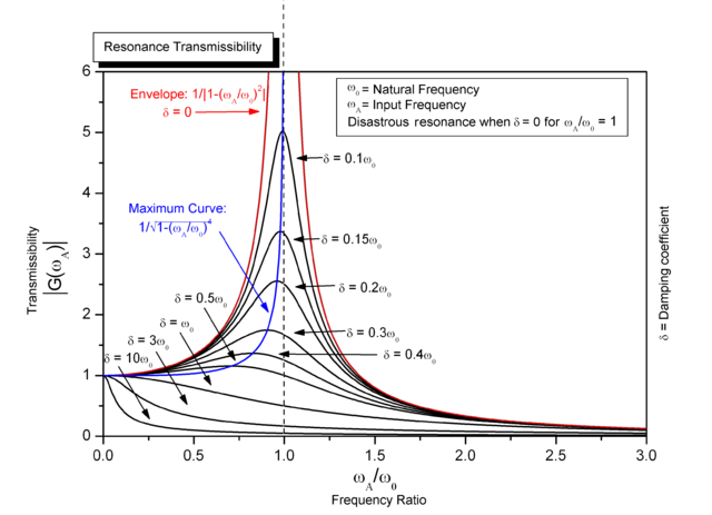
Top images from around the web for Understanding Quality Factor and Bandwidth
Factor de calidad - Wikipedia, la enciclopedia libre View original
Is this image relevant?
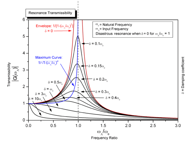
Rezonancija (fizika) — Википедија View original
Is this image relevant?
Q factor - Wikipedia View original
Is this image relevant?
Factor de calidad - Wikipedia, la enciclopedia libre View original
Is this image relevant?
Rezonancija (fizika) — Википедија View original
Is this image relevant?
Understanding Quality Factor and Bandwidth
- Quality factor (Q) measures the efficiency of energy storage in a resonant circuit
- Q factor calculated as the ratio of energy stored to energy dissipated per cycle
- Higher Q values indicate lower energy losses and sharper resonance peaks
- Bandwidth represents the frequency range where a circuit's response remains strong
- Calculated as the difference between upper and lower cutoff frequencies
- Inversely proportional to Q factor, expressed as
- Half-power points define the bandwidth limits where power drops to half its maximum value
- Correspond to frequencies where the response is 3 dB below the peak
Selectivity and Resonance Characteristics
- Selectivity describes a circuit's ability to discriminate between different frequencies
- Higher selectivity allows better isolation of desired signals from nearby interfering signals
- Directly related to Q factor, with higher Q values indicating greater selectivity
- Sharpness of resonance refers to the narrowness of the resonance peak
- Characterized by the steepness of the response curve near the resonant frequency
- Sharper resonance enables more precise tuning and better frequency discrimination
- Q factor serves as a measure of resonance sharpness, with higher Q indicating sharper peaks

Practical Applications and Considerations
- High Q circuits used in applications requiring precise frequency selection (radio tuners)
- Low Q circuits employed where broader frequency response is needed (audio amplifiers)
- Bandwidth considerations crucial in communication systems for determining data transmission rates
- Trade-off exists between selectivity and bandwidth in circuit design
- Adjusting component values allows tailoring of Q factor and bandwidth to specific requirements
- Quality factor impacts the transient response and settling time of resonant circuits
Energy and Damping

Energy Storage and Dissipation in Resonant Circuits
- Resonant circuits store energy alternately in electric and magnetic fields
- Capacitors store energy in electric fields, while inductors store energy in magnetic fields
- Total energy oscillates between these two forms at the resonant frequency
- Energy dissipation occurs due to resistance in the circuit
- Resistive elements convert electrical energy into heat through Joule heating
- Energy dissipation rate determines the decay of oscillations in the absence of external driving force
- Q factor quantifies the balance between energy storage and dissipation
- Higher Q indicates more energy stored relative to energy dissipated per cycle
Damping Effects and Circuit Behavior
- Damping refers to the reduction of oscillation amplitude over time
- Caused by energy dissipation mechanisms in the circuit
- Underdamped systems exhibit decaying oscillations (most resonant circuits)
- Critically damped systems return to equilibrium fastest without oscillation
- Overdamped systems approach equilibrium slowly without oscillation
- Damping factor (ζ) quantifies the degree of damping in a system
- Related to Q factor by the equation
- Lower damping (higher Q) results in longer-lasting oscillations and sharper resonance
Q-Factor Calculation and Analysis
- Q factor calculated using various formulas depending on circuit configuration
- For series RLC circuit:
- For parallel RLC circuit:
- Q factor also expressed in terms of energy:
- Can be determined from frequency response curve using bandwidth:
- Q factor analysis helps in predicting circuit behavior and optimizing performance
- Used to estimate ringdown time of oscillations:
- Higher Q circuits require more careful tuning due to increased sensitivity to component variations
See Fiveable more often in Google
Mark Fiveable as a preferred source and Google is more likely to show you our guides in Top Stories, with a "preferred" badge in AI Mode and AI Overviews.