Operational amplifiers are the workhorses of analog circuits. They're versatile components that can amplify, filter, and manipulate signals in countless ways. Understanding their basics is key to mastering more complex applications in active filters and signal processing.
In this section, we'll cover the fundamentals of op-amps, including their ideal characteristics and practical limitations. We'll also explore common configurations like inverting and non-inverting amplifiers, and dive into key performance metrics that affect real-world circuit design.
Operational Amplifier Basics
Fundamental Concepts and Characteristics
Top images from around the web for Fundamental Concepts and Characteristics
Operational Amplifier Basics - Electronics-Lab.com View original
Is this image relevant?
Operational Amplifier Basics - Electronics-Lab.com View original
Is this image relevant?
Operational Amplifier Basics - Electronics-Lab.com View original
Is this image relevant?
Operational Amplifier Basics - Electronics-Lab.com View original
Is this image relevant?
Operational Amplifier Basics - Electronics-Lab.com View original
Is this image relevant?
1 of 3
Operational amplifier functions as a high-gain electronic voltage amplifier with differential inputs and a single output
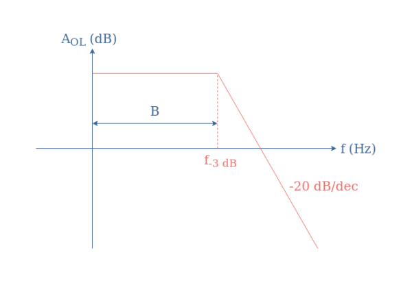
Open-loop gain represents the amplification factor of an op-amp without feedback, typically very high (100,000 or more)
Closed-loop gain refers to the amplification when negative feedback is applied, providing stable and predictable operation
Input offset voltage measures the small voltage difference between inputs required to produce zero output voltage
Bandwidth indicates the range of frequencies an op-amp can amplify effectively, usually decreasing as gain increases
Ideal Op-Amp Assumptions
Infinite open-loop gain allows for simplified circuit analysis
Infinite input impedance results in negligible input current
Zero output impedance enables the op-amp to drive various loads
Infinite bandwidth permits operation at all frequencies
Zero input offset voltage ensures accurate amplification of small signals
Practical Op-Amp Considerations
Finite open-loop gain limits maximum achievable amplification
Input bias currents affect circuit performance, especially in high-impedance applications
Power supply voltages constrain the maximum output voltage swing
Temperature variations can impact op-amp performance characteristics
Inverting and Non-Inverting Configurations
Inverting Amplifier Circuit
Inverting amplifier configuration inverts the input signal polarity
Input signal connects to the inverting input through a resistor
Feedback resistor connects the output to the inverting input
Gain determined by the ratio of feedback resistor to input resistor
Virtual ground concept applies to the inverting input
Closed-loop gain equation: Av=−RinRf
Non-Inverting Amplifier Circuit
Non-inverting amplifier configuration maintains input signal polarity
Input signal connects directly to the non-inverting input
Feedback network consists of two resistors forming a voltage divider
Gain determined by the ratio of resistors in the feedback network
Virtual short concept applies between the inputs
Closed-loop gain equation: Av=1+R1Rf
Virtual Ground and Virtual Short Principles
Virtual ground in inverting configuration keeps inverting input at ground potential
Virtual short in non-inverting configuration equalizes voltages at both inputs
These principles simplify circuit analysis and design
Enable accurate prediction of circuit behavior
Facilitate the application of negative feedback for stable operation
Key Performance Characteristics
Slew Rate and Its Impact
Slew rate defines the maximum rate of change of the output voltage
Measured in volts per microsecond (V/μs)
Limits the amplifier's ability to track rapidly changing input signals
Affects large-signal bandwidth and distortion in high-frequency applications
Can be a critical factor in selecting op-amps for specific applications (video processing)
Common-Mode Rejection Ratio (CMRR)
CMRR measures an op-amp's ability to reject common-mode signals
Expressed in decibels (dB), higher values indicate better performance
Crucial for differential amplifier applications (instrumentation amplifiers)
Impacts the accuracy of measurements in the presence of noise or interference
Calculated as the ratio of differential gain to common-mode gain
CMRR equation: CMRR=20log10AcmAd
Additional Performance Metrics
Input impedance affects the loading of signal sources
Output impedance influences the ability to drive various loads
Power supply rejection ratio (PSRR) measures immunity to power supply variations
Noise characteristics impact the minimum detectable signal level
Temperature coefficients describe performance changes with temperature variations
Key Terms to Review (18)
Positive feedback: Positive feedback is a process where the output of a system amplifies its own input, leading to an increase in activity or effect within the system. This mechanism can lead to exponential growth or runaway effects, significantly influencing the behavior of electronic circuits and systems. In many cases, positive feedback can enhance performance, but it also risks instability if not controlled properly.
Negative feedback: Negative feedback is a process in control systems where the output of a system is fed back in a way that reduces the overall output. This mechanism helps stabilize systems by automatically correcting deviations from a desired level. It plays a crucial role in various applications, enabling improved accuracy and stability in performance.
Integrator Circuit: An integrator circuit is an electronic circuit that performs mathematical integration of the input signal, producing an output voltage that represents the accumulated area under the input signal curve over time. This circuit is often built using operational amplifiers, which enable the conversion of a voltage input into a corresponding output that reflects the integral of the input signal, making it useful in applications like analog computing and signal processing.
Thévenin's Theorem: Thévenin's Theorem states that any linear electrical network with voltage sources, current sources, and resistors can be replaced by an equivalent circuit consisting of a single voltage source in series with a resistor. This simplification is particularly useful for analyzing complex circuits, especially when dealing with operational amplifiers, as it allows for easier calculation of circuit responses by focusing on one portion of the circuit at a time.
Real op-amp: A real op-amp is an operational amplifier that considers practical characteristics such as finite gain, input and output impedance, bandwidth limitations, and non-ideal behaviors that differ from the ideal op-amp model. These characteristics play a crucial role in determining how the op-amp will perform in actual circuit applications, affecting accuracy, stability, and overall functionality.
Slew Rate: Slew rate is a measure of how quickly an amplifier can respond to rapid changes in input signal, defined as the maximum rate of change of the output voltage per unit time, typically expressed in volts per microsecond (V/µs). It is crucial for determining how accurately an amplifier can handle fast signals without distortion, impacting both the frequency response and performance of analog signal processing.
Ideal op-amp: An ideal op-amp is a theoretical operational amplifier that possesses infinite open-loop gain, infinite input impedance, zero output impedance, and infinite bandwidth. This means it can amplify any input signal without distortion and does not load down the input source. The characteristics of an ideal op-amp make it a foundational concept for understanding how real op-amps function and are used in various applications.
Voltage Follower: A voltage follower, also known as a buffer amplifier, is an operational amplifier configuration that provides high input impedance and low output impedance, effectively transferring a voltage from one point to another without loading down the source. This configuration is crucial for isolating different stages of a circuit, allowing for signal integrity and minimizing distortion or attenuation.
Common-Mode Rejection Ratio: The common-mode rejection ratio (CMRR) is a measure of an operational amplifier's ability to reject input signals that are common to both its inverting and non-inverting inputs. It quantifies how well the op-amp can differentiate between the desired differential signal and unwanted noise or interference that appears on both inputs. A high CMRR indicates better performance, as it means the op-amp can effectively amplify the desired signal while minimizing the effect of common noise.
Input Impedance: Input impedance refers to the measure of resistance and reactance that an input port presents to a signal source. It is crucial in determining how much of an input signal is absorbed by the system versus how much is transmitted. High input impedance is generally desirable in electronic circuits, especially in analog signal processing, as it minimizes loading effects on the preceding stages, thus preserving signal integrity.
Non-inverting amplifier: A non-inverting amplifier is a type of operational amplifier (op-amp) configuration that amplifies an input signal while maintaining its phase, meaning the output is in phase with the input. This configuration is widely used in analog signal processing because it offers high input impedance, low output impedance, and the ability to amplify signals without inverting their polarity. The gain of the non-inverting amplifier can be adjusted by using resistors in a feedback loop, providing versatility in signal conditioning.
Inverting amplifier: An inverting amplifier is a type of operational amplifier configuration that produces an output voltage that is inversely proportional to the input voltage. This means that when the input voltage increases, the output voltage decreases, and vice versa. This configuration is widely used in analog signal processing for its ability to amplify signals while inverting their phase, making it essential for various applications in circuit design.
Gain: Gain refers to the ratio of output signal power to input signal power in a circuit, indicating how much a system amplifies a signal. It is a crucial concept in understanding how circuits process signals, especially in applications involving filters, operational amplifiers, and analog signal processing. The gain can be expressed in linear terms or in decibels (dB), and it plays a vital role in determining the performance and characteristics of various electronic systems.
Capacitor: A capacitor is a passive electronic component that stores electrical energy in an electric field, created by a pair of conductive plates separated by an insulating material known as a dielectric. Capacitors play a crucial role in various electrical and electronic applications, influencing behaviors such as energy storage, filtering, and timing within circuits.
Resistor: A resistor is a passive electrical component that resists the flow of electric current, converting electrical energy into heat. It plays a vital role in controlling current and voltage levels in circuits, impacting how components work together. Resistors are essential for setting bias points in active devices, limiting current to protect components, and shaping signals within various electronic applications.
Norton's Theorem: Norton's Theorem states that any linear electrical network with voltage sources and resistances can be replaced by an equivalent circuit consisting of a single current source in parallel with a single resistor. This theorem simplifies the analysis of complex circuits, allowing for easier calculation of current and voltage across specific components.
Superposition Theorem: The superposition theorem states that in a linear circuit with multiple independent sources, the total response (voltage or current) at any point in the circuit is the sum of the responses caused by each independent source acting alone, while all other independent sources are turned off. This principle is essential for analyzing complex circuits, as it allows for simpler calculations by considering one source at a time.
Nodal Analysis: Nodal analysis is a systematic method used to determine the voltage at each node in an electrical circuit. This technique relies on Kirchhoff's Current Law (KCL) and is especially useful in circuits with multiple components, allowing for the calculation of unknown voltages and currents efficiently by setting up a system of equations based on the nodes of the circuit.