Comparators and oscillators are essential building blocks in analog circuits. They enable voltage level detection, signal generation, and timing control. These components find applications in various systems, from simple LED flashers to complex communication devices.

This section explores different types of comparators and oscillators, including Schmitt triggers and multivibrators. We'll dive into their operating principles, design considerations, and practical applications, expanding our understanding of op-amp circuits beyond basic amplification.

Comparators and Hysteresis

Comparator Fundamentals and Applications

Top images from around the web for Comparator Fundamentals and Applications
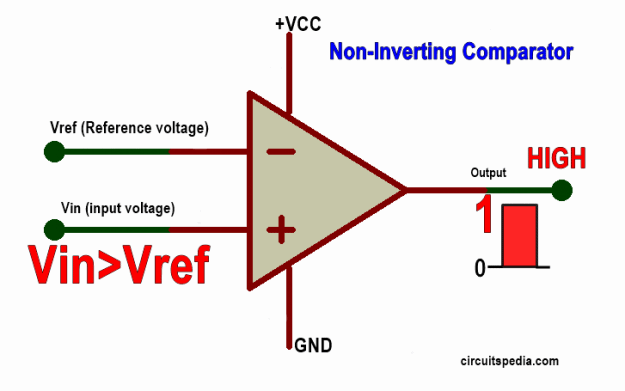
  • Comparators compare two input voltages and produce a binary output
  • Open-loop op-amps often used as comparators due to high gain
  • Output switches between positive and negative saturation voltages
  • Applications include level detection, zero-crossing detection, and analog-to-digital conversion
  • Comparators susceptible to noise, especially near threshold voltages
  • Noise can cause rapid output switching, known as chattering

Schmitt Trigger and Hysteresis Implementation

  • improves comparator performance by adding
  • Hysteresis creates two distinct threshold voltages for rising and falling inputs
  • Upper threshold voltage (VUT) triggers high output when input exceeds it
  • Lower threshold voltage (VLT) triggers low output when input falls below it
  • Hysteresis width equals the difference between VUT and VLT
  • loop in Schmitt trigger circuit creates hysteresis effect
  • Resistor values in feedback network determine hysteresis width

Benefits and Applications of Hysteresis

  • Hysteresis reduces sensitivity to noise and prevents output oscillation
  • Improves stability in control systems and signal processing circuits
  • Schmitt triggers used in wave shaping, pulse generation, and signal conditioning
  • Applications include switch debouncing, voltage level detection with noise immunity
  • Hysteresis loop provides memory effect, useful in certain control applications
  • Adjustable hysteresis allows customization for specific noise environments

Multivibrator Circuits

Astable Multivibrator Design and Operation

  • Astable multivibrators generate continuous square wave output without external trigger
  • Circuit consists of two cross-coupled transistors or op-amps
  • Operates in free-running mode, continuously switching between two unstable states
  • Frequency determined by RC time constants in the circuit
  • Duty cycle can be adjusted by varying resistor values
  • Applications include clock generators, LED flashers, and tone generators
  • Can produce non-symmetrical waveforms by using different time constants for each state

Monostable Multivibrator Characteristics

  • Monostable multivibrators produce a single pulse of predetermined duration
  • Also known as one-shot or single-shot multivibrators
  • Triggered by an external input signal
  • Output pulse width determined by RC time constant in the circuit
  • Returns to stable state after pulse duration expires
  • Used for pulse shaping, timing control, and edge detection in digital systems
  • Can be retriggerable or non-retriggerable, affecting response to multiple input triggers

Oscillator Circuits

Wien Bridge Oscillator Principles

  • Wien bridge oscillators generate low-distortion sine waves
  • Consists of a Wien bridge network and an op-amp with positive feedback
  • Bridge network acts as a frequency-selective element
  • Oscillation frequency determined by RC values in the bridge: f=12πRCf = \frac{1}{2\pi RC}
  • Amplitude stabilization achieved through or nonlinear elements
  • Used in audio signal generation, function generators, and test equipment
  • Provides good frequency stability and low harmonic distortion

Phase-Shift Oscillator Design

  • Phase-shift oscillators use RC network to create necessary phase shift for oscillation
  • Typically employ three RC stages, each providing 60° phase shift
  • Total phase shift of 180° combined with inverting amplifier creates positive feedback
  • Oscillation frequency determined by RC values: f12πRC6f \approx \frac{1}{2\pi RC\sqrt{6}}
  • Simple design with fewer components compared to
  • Used in low-frequency applications and educational demonstrations
  • Limited amplitude stability may require additional control mechanisms

Voltage-Controlled Oscillator (VCO) Operation

  • VCOs produce an output frequency proportional to an input control voltage
  • Employ variable reactance elements (varactors) or current-controlled oscillators
  • Linear VCOs maintain a linear relationship between control voltage and frequency
  • Tuning range defines the frequency span controlled by the input voltage
  • Key component in phase-locked loops (PLLs) and frequency modulation systems
  • Applications include frequency synthesis, FM radio, and clock recovery circuits
  • VCO quality factors include tuning linearity, phase noise, and frequency stability

Key Terms to Review (21)

Astable multivibrator: An astable multivibrator is a type of electronic oscillator that continuously switches between its high and low states without requiring any external triggering. This makes it a fundamental building block in generating square wave signals, commonly used in timers, clocks, and pulse generation applications. The astable multivibrator utilizes two active devices (like transistors or operational amplifiers) and feedback to create a self-sustaining oscillation.
Differentiator circuit: A differentiator circuit is an electronic circuit that produces an output voltage that is proportional to the rate of change of the input voltage. This means it effectively calculates the derivative of the input signal, making it useful in applications where the detection of rapid changes in signal is essential. Differentiator circuits can be implemented using operational amplifiers and are commonly used in signal processing, control systems, and waveform shaping.
Gain Margin: Gain margin is a key measure of the stability of a feedback control system, defined as the amount by which the gain of the system can be increased before it reaches instability. It quantifies how much the gain can change before the system's response shifts from stable to unstable, and is closely related to concepts like transfer functions, frequency response, and Bode plots, which help in analyzing system behavior in the frequency domain.
Hysteresis: Hysteresis refers to the phenomenon where the response of a system depends on its history, particularly in the context of input-output relationships. In electrical circuits, hysteresis is often observed in devices like comparators and oscillators, where the output state can be influenced by past input levels, leading to a lag or a difference in response depending on whether the input is increasing or decreasing. This characteristic is crucial for creating stable and reliable switching behavior in various applications.
Inductor: An inductor is a passive electrical component that stores energy in a magnetic field when an electric current passes through it. This component plays a crucial role in various circuit applications, influencing how circuits respond to changes in voltage and current over time.
Integrator Circuit: An integrator circuit is an electronic circuit that performs mathematical integration of the input signal, producing an output voltage that represents the accumulated area under the input signal curve over time. This circuit is often built using operational amplifiers, which enable the conversion of a voltage input into a corresponding output that reflects the integral of the input signal, making it useful in applications like analog computing and signal processing.
Inverting Comparator: An inverting comparator is an electronic circuit that compares two input voltages and outputs a digital signal based on the comparison. If the voltage at the inverting input is greater than the voltage at the non-inverting input, the output switches to a low state; otherwise, it switches to a high state. This fundamental behavior makes it essential in various applications, such as analog-to-digital conversion and signal conditioning.
Monostable multivibrator: A monostable multivibrator is a type of electronic circuit that has one stable state and one unstable state, producing a single output pulse when triggered. It is commonly used to generate precise timing intervals and pulse widths in various applications, functioning as a timer or pulse generator. This circuit can convert a brief input signal into a longer output pulse, making it essential for timing applications and waveform shaping.
Negative feedback: Negative feedback is a process in control systems where the output of a system is fed back in a way that reduces the overall output. This mechanism helps stabilize systems by automatically correcting deviations from a desired level. It plays a crucial role in various applications, enabling improved accuracy and stability in performance.
Non-inverting comparator: A non-inverting comparator is an electronic circuit that compares two input voltages and outputs a signal based on which voltage is higher. This type of comparator uses a non-inverting configuration, meaning that the input voltage applied to the non-inverting terminal is directly reflected in the output when it exceeds the reference voltage at the inverting terminal. Non-inverting comparators are essential in various applications such as signal conditioning, level detection, and as building blocks for oscillators.
Phase Margin: Phase margin is a stability criterion in control systems that indicates how much additional phase lag can be tolerated before the system becomes unstable. It represents the difference between the phase of the open-loop transfer function and -180 degrees at the gain crossover frequency, where the magnitude of the transfer function is equal to one. A higher phase margin generally indicates a more stable system.
Phase-locked loop: A phase-locked loop (PLL) is an electronic circuit that synchronizes an output signal's phase with that of a reference signal. It is widely used in communication systems to stabilize frequencies and maintain a constant phase relationship between signals. By comparing the phase of the output and reference signals, the PLL can adjust the frequency of a voltage-controlled oscillator, allowing for precise control and improved signal integrity.
Phase-shift oscillator: A phase-shift oscillator is a type of electronic oscillator that generates a continuous waveform, typically a sine wave, through the use of an amplifier and a phase-shifting network. This oscillator works by introducing a total phase shift of 360 degrees around the loop, which allows for sustained oscillations. It relies on passive components like resistors and capacitors to create the necessary phase shifts, making it simple and effective for producing low-frequency signals.
Positive feedback: Positive feedback is a process where the output of a system amplifies its own input, leading to an increase in activity or effect within the system. This mechanism can lead to exponential growth or runaway effects, significantly influencing the behavior of electronic circuits and systems. In many cases, positive feedback can enhance performance, but it also risks instability if not controlled properly.
Relaxation oscillator: A relaxation oscillator is a type of electronic oscillator that generates a non-sinusoidal waveform, typically a square or sawtooth wave, through the periodic charging and discharging of a capacitor. It operates by alternately storing energy in an electric field and then releasing it, creating a repetitive cycle that results in oscillations. This process is often controlled by a comparator, which switches states when the voltage across the capacitor reaches specific thresholds.
Resistor-capacitor network: A resistor-capacitor (RC) network is an electrical circuit consisting of resistors and capacitors connected in various configurations. This type of network is significant because it can create filters, oscillators, and timing circuits that manipulate signals in a variety of applications, showcasing how resistors and capacitors interact to affect voltage and current over time.
Schmitt Trigger: A Schmitt Trigger is a type of comparator circuit that incorporates positive feedback to provide hysteresis, allowing it to produce a clean output signal even with noisy input signals. This means it can change its output state at different input voltage levels, which helps eliminate unwanted fluctuations in digital circuits. The Schmitt Trigger is commonly used in applications like waveform shaping and generating square waves.
Triangle wave generator: A triangle wave generator is an electronic circuit that produces a triangular waveform, characterized by a linear rise and fall in voltage over time. This type of waveform is essential in various applications, including signal processing and waveform synthesis, and serves as a basis for generating other types of waveforms, like sawtooth and square waves. Triangle wave generators often utilize operational amplifiers or comparators to achieve the desired output.
Voltage-Controlled Oscillator: A voltage-controlled oscillator (VCO) is an electronic circuit that generates a periodic signal, usually a sine wave or square wave, whose frequency can be adjusted by varying the input voltage. This ability to change frequency based on input voltage makes VCOs essential in applications such as modulation, frequency synthesis, and signal processing, connecting to the concepts of comparators and oscillators.
Wien Bridge Oscillator: The Wien Bridge Oscillator is a type of electronic oscillator that generates sine waves using a bridge circuit and is known for its ability to produce low-distortion signals. It employs a combination of resistors and capacitors to form the bridge, allowing it to operate at a specific frequency determined by these components. This oscillator is widely used in audio applications, function generators, and as a precise frequency source due to its stability and ease of adjustment.
Zero-crossing detector: A zero-crossing detector is an electronic circuit that identifies the point at which a signal crosses zero volts, indicating a change in polarity. This circuit is crucial in applications such as phase-locked loops and can be implemented using comparators to convert analog signals into digital signals for further processing. By detecting zero crossings, the circuit enables precise timing and synchronization in various electronic systems.
© 2024 Fiveable Inc. All rights reserved.
AP® and SAT® are trademarks registered by the College Board, which is not affiliated with, and does not endorse this website.