⚙️AP Physics C: Mechanics
⚙️AP Physics C: Mechanics
FRQ 1 – Mathematical Routines
Unit 1: Kinematics
Practice FRQ 1 of 81/8
1. A model rocket of mass m is launched vertically upward from the ground. The rocket engine produces a time-varying net upward acceleration (accounting for gravity) given by for , where is the initial net acceleration and T is the time when the engine shuts off. At time , the engine shuts off and the rocket continues upward, subject only to gravity. Let the upward direction be positive, and let be the position of the rocket at . Figure 1 shows the rocket at three stages of motion.
Figure 1: Model rocket at launch, engine shutoff, and maximum height (upward is +y)
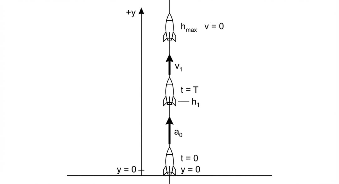
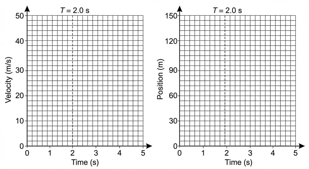
Figure 2: Blank axes for velocity–time and position–time sketches (engine shuts off at T = 2.0 s)
A.
i. On the axes in Figure 2, sketch graphs of the rocket's velocity versus time and position versus time for the entire motion from launch until the rocket reaches its maximum height. The engine shuts off at time s. Clearly indicate on your graphs:
• The time T when the engine shuts off
• The qualitative shape of each curve in both the engine-on and engine-off phases
• The maximum height on the position graph
ii. Derive an expression for the rocket's velocity at time when the engine shuts off. Express your answer in terms of , T, and physical constants, as appropriate. Begin your derivation by writing a fundamental physics principle or an equation from the reference information.
After the engine shuts off at , the rocket continues upward under the influence of gravity alone until reaching its maximum height .
B. Derive an expression for the maximum height reached by the rocket, measured from the ground. Express your answer in terms of , T, g, and physical constants, as appropriate. Begin your derivation by writing a fundamental physics principle or an equation from the reference information.