Fiveable
💡AP Physics C: E&M
​

💡AP Physics C: E&M

FRQ 4 – Qualitative/Quantitative Translation
​
Unit 8: Electric Charges, Fields, and Gauss's Law
​
FRQ Types & Units

Each FRQ type tests specific skills taught in particular units. Here's why certain units appear for each question type:

This mapping reflects College Board's exam structure - each FRQ type tests specific skills that are taught in particular units.

Practice FRQ 1 of 201/20

4. A solid conducting sphere of radius R=0.10 mR=0.10\ \text{m}R=0.10 m is centered at the origin and carries a net free charge +Q=4.0 μC+Q=4.0\ \mu\text{C}+Q=4.0 μC placed on the conductor. Surrounding the conductor is a concentric spherical shell of dielectric material that extends from radius RRR to radius 2R=0.20 m2R=0.20\ \text{m}2R=0.20 m and has relative permittivity κ=4.0\kappa=4.0κ=4.0. Outside the dielectric shell (for r>2Rr>2Rr>2R) is vacuum. A point PPP is located on the +x+x+x-axis at radius rP=0.15 mr_P=0.15\ \text{m}rP​=0.15 m (within the dielectric). A small test particle of mass m=2.0 gm=2.0\ \text{g}m=2.0 g and charge q=+1.0 μCq=+1.0\ \mu\text{C}q=+1.0 μC can be placed at point PPP. Neglect any effects of air and assume electrostatic equilibrium.

Figure 1. Conducting sphere with surrounding dielectric shell (κ = 4.0) and point P located within the dielectric at rP = 0.15 m on the +x-axis.

Create a clean, black-and-white physics cross-section diagram (2D) representing a spherical, radially symmetric electrostatics setup.

Overall layout and orientation:
- Show a square or rectangular drawing area with the geometry centered.
- Draw a horizontal axis through the center of the figure and label it as the x-axis.
- Put an arrowhead at the right end of this axis and label that direction "+x".
- Mark the exact center of the concentric spheres with a small filled dot and label it "O" (the origin).

Concentric boundaries (must be perfectly centered on O):
1) Inner conductor boundary (radius R):
- Draw a perfect circle centered on O representing the surface of the solid conducting sphere.
- Place the label "Conductor" inside this inner circle.
- Add a separate label near the inner circle that reads exactly: "R = 0.10 m".
- Indicate that the conductor carries net free charge by placing multiple small plus signs distributed evenly along the circumference of the inner circle (on the surface, not inside the material) and add a label with a leader line pointing to the surface that reads exactly: "+Q = 4.0 μC".

2) Outer dielectric boundary (radius 2R):
- Draw a second perfect circle centered on O, larger than the first, representing the outer surface of the dielectric shell.
- Ensure the space between the two circles is a uniform-thickness annulus.
- Add a label near the outer circle that reads exactly: "2R = 0.20 m".

Material regions (explicitly label each region):
- Region r < R (inside the inner circle): label clearly as "Solid conducting sphere".
- Region R < r < 2R (the annular ring between the circles): label clearly as "Dielectric" and include the text "κ = 4.0" inside the annulus.
- Region r > 2R (outside the outer circle): label clearly as "Vacuum".

Point P location (must be unambiguous and numerically anchored):
- Place point P on the +x-axis (the horizontal line to the right of O).
- The point must lie strictly within the dielectric annulus (between the inner and outer circles), not on either boundary.
- Mark P with a small filled dot and label it "P".
- Add a text label adjacent to P that reads exactly: "rP = 0.15 m".
- Draw a thin radial line segment along the +x-axis from O to P to emphasize the radial distance, and place the label "rP" centered along that line segment.

Radial ordering clarity (avoid ambiguity):
- Near the +x-axis, include three small tick marks where the +x-axis intersects (i) the inner circle, (ii) point P, and (iii) the outer circle.
- Label these three locations in increasing distance from O as: "r = R", "r = rP", and "r = 2R" respectively (with short leader lines or adjacent text).

Styling constraints:
- Use solid black lines for both circles and the x-axis.
- Use consistent font for all labels.
- No grid, no shading gradients; if you use shading, use a very light, uniform hatch pattern only in the dielectric annulus to distinguish it from the conductor and vacuum.
- Ensure all numeric text appears exactly as: "R = 0.10 m", "2R = 0.20 m", "κ = 4.0", "+Q = 4.0 μC", and "rP = 0.15 m".
A.

FEF_EFE​ 
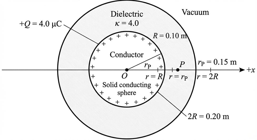
is the magnitude of the electric force on the test charge qqq when it is placed at point PPP in the situation shown in Figure 1 (dielectric shell present). FgF_gFg​ is the magnitude of the gravitational force on the test particle.

Indicate whether FEF_EFE​ is greater than, less than, or equal to FgF_gFg​ by writing one of the following.

  • FE>FgF_E > F_gFE​>Fg​
  • FE<FgF_E < F_gFE​<Fg​
  • FE=FgF_E = F_gFE​=Fg​

Justify your answer.

B.

Derive an expression for the magnitude EPE_PEP​ of the electric field at point PPP (where R<rP<2RR<r_P<2RR<rP​<2R) in terms of QQQ, rPr_PrP​, κ\kappaκ, and physical constants, as appropriate. Begin your derivation by writing a fundamental physics principle or an equation from the reference information.

Figure 2. Same concentric-sphere geometry as Figure 1, but the region R < r < 2R is vacuum (κ = 1) instead of dielectric; point P remains at rP = 0.15 m on the +x-axis.
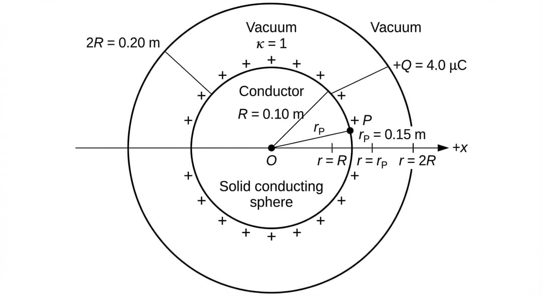
Create a clean, black-and-white physics cross-section diagram (2D) with the same centered geometry and axis orientation as Figure 1, but with the dielectric removed.

Overall layout and orientation:
- Center the geometry in the drawing.
- Draw the horizontal x-axis through the center.
- Put an arrowhead at the right end and label that direction "+x".
- Mark the center with a small filled dot and label it "O".

Concentric boundaries (must be perfectly centered on O):
1) Inner conductor boundary (radius R):
- Draw a perfect circle centered on O for the surface of the solid conducting sphere.
- Label inside this circle: "Conductor".
- Add a nearby label that reads exactly: "R = 0.10 m".
- Place multiple small plus signs evenly around the inner circle’s circumference to indicate surface charge.
- Add a label with a leader line pointing to the conductor surface that reads exactly: "+Q = 4.0 μC".

2) Outer reference boundary (radius 2R):
- Draw a second perfect circle centered on O, larger than the first, to mark the radius 2R boundary.
- Add a nearby label that reads exactly: "2R = 0.20 m".

Material regions (explicitly label each region):
- Region r < R: label as "Solid conducting sphere".
- Region R < r < 2R (the annulus between the circles): label as "Vacuum" and include the text "κ = 1" inside this annulus.
- Region r > 2R: also label as "Vacuum" (outside the outer circle).

Point P location (numerically anchored and identical placement logic to Figure 1):
- Place point P on the +x-axis, to the right of O.
- Ensure P lies strictly between the inner and outer circles (R < rP < 2R).
- Mark P with a small filled dot and label it "P".
- Add a text label next to P that reads exactly: "rP = 0.15 m".
- Draw a thin radial line segment along the +x-axis from O to P and label that segment "rP".

Radial ordering clarity:
- On the +x-axis, include three small tick marks at the intersections with the inner circle, at point P, and at the intersection with the outer circle.
- Label these positions (in increasing distance from O): "r = R", "r = rP", and "r = 2R".

Styling constraints:
- Use solid black lines for circles and axis.
- No gradients; optionally use a very light hatch pattern ONLY to distinguish the annulus region, but it must still be labeled "Vacuum" with "κ = 1".
- Ensure all numeric text appears exactly as: "R = 0.10 m", "2R = 0.20 m", "κ = 1", "+Q = 4.0 μC", and "rP = 0.15 m".
C.

Indicate whether FnewF_{\text{new}}Fnew​ is greater than, less than, or equal to FEF_EFE​ by writing one of the following. The dielectric shell is removed and replaced by vacuum, as shown in Figure 2, so that κ=1\kappa=1κ=1 for R<r<2RR<r<2RR<r<2R. The conductor still has net free charge +Q+Q+Q. The test charge qqq is again placed at the same point PPP at radius rP=0.15 mr_P=0.15\ \text{m}rP​=0.15 m. Let FnewF_{\text{new}}Fnew​ be the new magnitude of the electric force on the test charge.

  • Fnew>FEF_{\text{new}} > F_EFnew​>FE​
  • Fnew<FEF_{\text{new}} < F_EFnew​<FE​
  • Fnew=FEF_{\text{new}} = F_EFnew​=FE​

Briefly justify your answer by referencing your derivation in part B.


Pep

essential ap study content awaits..

Features
Testimonials
Testimonials
start studying →
FRQ Directions
Free Response Question Practice

This practice environment simulates the AP AP Physics C: E&M Free Response Questions section. Here are some guidelines:

  • Read each question carefullybefore responding. Pay attention to command verbs like "identify," "explain," "analyze," or "evaluate."
  • Use the timer to practice time management. You can pause, restart, or hide the timer as needed.
  • Mark for Review if you want to come back to a question later.
  • Your responses are saved automatically as you type. You can also use the drawing tool for questions that require diagrams or graphs.
  • Use the toolbar for formatting options like bold, italic, subscript, and superscript.
  • Navigate between questions using the Previous and Next buttons at the bottom of the screen.

Tip: Answer all parts of each question. Partial credit is often available, so even if you are unsure, provide what you know.