The stiffness matrix method revolutionizes structural analysis by using matrices to represent beam and frame behavior. It connects forces and displacements, allowing for efficient computation of complex structures. This approach is crucial for understanding how loads affect beams and frames.
This method builds on earlier concepts in the chapter, extending matrix analysis to more complex structural elements. It provides a powerful tool for engineers to analyze and design buildings, bridges, and other structures, forming the foundation for modern structural analysis software.
Element Stiffness Matrices
Beam and Frame Element Matrices
Top images from around the web for Beam and Frame Element Matrices
New Formula for Geometric Stiffness Matrix Calculation View original
Is this image relevant?
Frontiers | Vibration Suppression Through Variable Stiffness and Damping Structural Joints View original
Is this image relevant?
Frontiers | Frequency-Domain Physical-Parameter System Identification of Building Structures ... View original
Is this image relevant?
New Formula for Geometric Stiffness Matrix Calculation View original
Is this image relevant?
Frontiers | Vibration Suppression Through Variable Stiffness and Damping Structural Joints View original
Is this image relevant?
1 of 3
stiffness matrix represents the relationship between applied forces and resulting displacements for a beam element
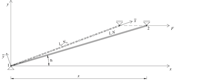
stiffness matrix extends the beam matrix to include axial forces and deformations
Both matrices are derived using the principle of virtual work and beam theory
Beam element stiffness matrix typically has a size of 4x4 for 2D analysis (two nodes, two degrees of freedom per node)
Frame element stiffness matrix usually has a size of 6x6 for 2D analysis (two nodes, three degrees of freedom per node)
These matrices are symmetrical and positive definite, ensuring numerical stability in structural analysis
Degrees of Freedom and Deformation Relationships
Rotational degrees of freedom account for the angular displacement at beam ends
Moment-curvature relationship describes how bending moments affect the curvature of the beam
Shear deformation considers the effect of shear forces on the overall deformation of the element
Axial deformation incorporates the elongation or compression of the element due to axial forces
Each degree of freedom corresponds to a row and column in the stiffness matrix
Coupling between different degrees of freedom is represented by off-diagonal terms in the matrix
Matrix Assembly and Application
Element stiffness matrices are assembled into a for the entire structure
Assembly process involves mapping local element degrees of freedom to global structure degrees of freedom
Boundary conditions are applied to the global stiffness matrix to constrain specific degrees of freedom
The resulting system of equations is solved to determine nodal displacements and internal forces
Element stiffness matrices can be modified to account for material nonlinearity or geometric effects (large deformations)
Member Forces and Actions
Force Analysis and Load Distribution
Fixed-end forces represent the reactions at the ends of a member when its ends are fully restrained
These forces are calculated for various loading conditions (point loads, distributed loads, moments)
Member-end actions are the forces and moments acting at the ends of a structural member
They include axial forces, shear forces, and bending moments
Load vector represents the external forces applied to the structure in matrix form
It is assembled by combining the fixed-end forces and directly applied nodal loads
Reaction Analysis and Equilibrium
Nodal reactions are the forces and moments that develop at support points to maintain equilibrium
They are calculated by summing the member-end actions and applied loads at each node
are used to verify the accuracy of the computed reactions
Internal member forces can be determined from the nodal displacements and member stiffness properties
Shear force and bending moment diagrams are constructed using the computed member forces
Force Transformation and Coordinate Systems
Member forces are typically calculated in the local coordinate system of each element
Transformation matrices are used to convert forces between local and global coordinate systems
Global forces are necessary for assembling the structure's overall equilibrium equations
Local forces are used for member design and stress analysis
Proper force transformation ensures compatibility between connected elements and accurate load transfer
Joint Types
Rigid Joints and Their Characteristics
Rigid joints maintain the angle between connected members under loading
They transfer both forces and moments between connected elements
Rigid joints are modeled with continuity of all degrees of freedom (translations and rotations)
Commonly used in moment-resisting frames and continuous beams
Increase the overall stiffness and stability of the structure
Require special detailing in design to ensure adequate moment transfer capacity
Hinge Connections and Their Behavior
Hinge connections allow relative rotation between connected members
They transfer forces but not moments between elements
Modeled by releasing the rotational degree of freedom at the connection
Often used in truss structures, pin-ended columns, and simply supported beams
Reduce the overall stiffness of the structure but can be beneficial for allowing thermal expansion or reducing moment transfer
Simplify the analysis and design process in certain structural configurations
Comparison and Application of Joint Types
Choice between rigid and hinged connections depends on desired structural behavior and load transfer mechanisms
Rigid joints provide greater lateral stability but may require larger member sizes to resist moments
Hinge connections allow for more economical designs in some cases but may require additional bracing for stability
Mixed systems with both rigid and hinged connections are common in practice (semi-rigid frames)
Joint behavior significantly influences the distribution of internal forces and overall structural deformation
Accurate modeling of joint types is crucial for realistic structural analysis and design
Key Terms to Review (18)
Axial Stiffness: Axial stiffness refers to the resistance of a structural element to axial deformation under axial loads, such as tension or compression. It is a critical factor in analyzing the behavior of beams and frames, as it affects how structures respond to loads and ensures stability. The axial stiffness of an element is determined by its material properties and geometric characteristics, making it essential for understanding how structures will perform under various loading conditions.
Beam element: A beam element is a structural component used in engineering analysis to represent the behavior of beams under various loads and constraints. These elements are typically characterized by their length, cross-sectional area, and material properties, allowing engineers to model their bending, shear, and axial deformations accurately. Understanding beam elements is crucial for applying stiffness methods and formulating stiffness matrices for beams and frames.
Compatibility conditions: Compatibility conditions are mathematical requirements ensuring that the displacements or deformations in a structure are consistent with the internal forces and moments acting within it. These conditions are essential in maintaining equilibrium and ensuring that the structure behaves as intended under applied loads, affecting how internal force diagrams, degrees of indeterminacy, and various analysis methods are approached.
Determinant: A determinant is a scalar value that is calculated from the elements of a square matrix, providing important information about the matrix, such as whether it is invertible and the volume scaling factor of linear transformations. In structural analysis, determinants are essential for understanding properties of matrices, particularly in relation to solving systems of equations and analyzing the behavior of structures under various loads.
Equilibrium equations: Equilibrium equations are mathematical expressions that represent the balance of forces and moments acting on a structure. These equations ensure that a structure is stable and that it does not experience any unbalanced forces or moments, which is crucial for analyzing reactions, internal forces, and overall structural behavior.
Finite element method: The finite element method (FEM) is a numerical technique used to obtain approximate solutions to boundary value problems for partial differential equations. It divides complex structures into smaller, simpler parts called elements, which can be easily analyzed, making it especially useful for structural analysis in engineering.
Fixed support: A fixed support is a type of structural connection that prevents both translation and rotation at the point of support, effectively restraining a beam or structure from moving in any direction. This means that a structure with a fixed support will have zero displacement and zero rotation at that point, which is crucial for analyzing forces, reactions, and deflections in beams and frames.
Flexural Stiffness: Flexural stiffness is a measure of a structural element's resistance to bending under load, defined as the product of the element's modulus of elasticity and its moment of inertia. It plays a critical role in determining how beams and frames deform when subjected to loads, directly affecting their overall performance and safety. Understanding flexural stiffness is essential in evaluating the behavior of structures and optimizing their design for strength and stability.
Frame element: A frame element is a structural component used in the analysis and design of frames, which are assemblies of beams and columns designed to support loads. These elements play a crucial role in determining the overall stiffness and stability of the structure, as they connect at joints and transfer loads through axial forces, shear forces, and bending moments. Understanding frame elements is essential for accurately applying the stiffness matrix method, which allows engineers to evaluate the response of complex frames under various loading conditions.
Global stiffness matrix: The global stiffness matrix is a fundamental concept in structural analysis that represents the relationship between nodal displacements and applied forces in a structure. It is assembled from the individual stiffness matrices of elements in a structure, allowing for the analysis of complex systems like continuous beams, frames, trusses, and beams under various loading conditions. This matrix forms the backbone for formulating equations of equilibrium that govern the behavior of structures.
Local stiffness matrix: A local stiffness matrix is a representation of the relationship between nodal forces and displacements within an element in structural analysis. It encapsulates how an individual element responds to external loads, allowing for the assembly of a global system response when combined with other elements. This matrix is fundamental in finite element analysis, ensuring that the behavior of complex structures can be effectively modeled and analyzed.
Matrix displacement method: The matrix displacement method is a structural analysis technique that utilizes stiffness matrices to determine the displacements and reactions of structures under external loads. This approach is particularly effective for analyzing complex systems like beams and frames, where traditional methods may fall short. By formulating the structure in terms of its stiffness properties, this method allows for efficient computations and can easily accommodate various boundary conditions and loading scenarios.
Matrix transformation: Matrix transformation refers to the process of applying a mathematical operation, represented by a matrix, to a set of coordinates or vectors in order to perform various geometric manipulations like scaling, rotating, or translating. In the context of structural analysis, this concept is essential as it facilitates the analysis and design of beams and frames by allowing for systematic representation and computation of forces and displacements.
Modulus of Elasticity: The modulus of elasticity is a material property that measures a material's ability to deform elastically (i.e., non-permanently) when a stress is applied. It indicates how much a material will stretch or compress under load, which is crucial for understanding how structures respond to various forces and loads during analysis.
Moment of Inertia: The moment of inertia is a measure of an object's resistance to rotational motion about a specific axis. It depends on the mass distribution relative to that axis and plays a crucial role in calculating deflections, analyzing stresses, and designing structures, especially in the context of beams and frames.
Roller support: A roller support is a type of support that allows a structure to rotate and move horizontally while preventing vertical movement. It provides a reaction force perpendicular to the surface it rests on, making it essential in analyzing structures under various loading conditions, as it helps ensure stability and flexibility in beams and frames.
Stiffness equations: Stiffness equations are mathematical expressions that relate the displacements of a structure to the applied forces, reflecting the relationship between internal forces and deformations. These equations are essential in structural analysis as they help to determine how a structure will respond to various loads, particularly in beams and frames. Understanding these equations is crucial for designing stable and efficient structures, as they provide insights into the stiffness characteristics and overall behavior under load.
Superposition Principle: The superposition principle states that in a linear system, the total response at any point is equal to the sum of the individual responses caused by each load acting independently. This concept helps simplify the analysis of structures by allowing engineers to assess the effects of multiple loads separately before combining their effects to understand the overall behavior of the structure.