Closed-loop system analysis is crucial for understanding feedback control systems. It helps engineers evaluate stability, performance, and robustness of systems like PID controllers. This analysis involves techniques like Routh-Hurwitz and Nyquist criteria for stability assessment.
Performance metrics like steady-state error and transient response are key in closed-loop analysis. Gain and phase margins provide insights into system robustness. Root locus and Bode plots are valuable tools for visualizing system behavior and designing compensators to improve performance.
Closed-loop system stability
Routh-Hurwitz criterion
- Algebraic method for determining the stability of a closed-loop system based on the coefficients of its characteristic equation
- Provides necessary and sufficient conditions for the stability of a linear time-invariant (LTI) system
- Constructs a tabular array called the Routh table using the coefficients of the characteristic equation
- The number of sign changes in the first column of the Routh table indicates the number of unstable poles in the closed-loop system
Nyquist stability criterion
- Graphical method for determining the stability of a closed-loop system based on the open-loop frequency response
- Relates the encirclements of the -1 point on the complex plane by the open-loop frequency response to the number of unstable poles in the closed-loop system
- Can be applied to systems with time delays and non-minimum phase characteristics (right-half plane zeros)
- The Nyquist plot provides insights into the stability margins and robustness of the closed-loop system
- The Nyquist contour is a closed path that encircles the right-half of the complex plane, including the imaginary axis and an infinite semicircle
Closed-loop system performance
Steady-state error and system type
- Represents the difference between the desired output and the actual output of a closed-loop system in the steady-state condition
- The type of the system (Type 0, Type 1, or Type 2) determines the ability of the system to track different types of inputs (step, ramp, or parabolic) with zero steady-state error
- Type 0 systems have a finite steady-state error for step inputs and an infinite steady-state error for ramp and parabolic inputs
- Type 1 systems have zero steady-state error for step inputs, a finite steady-state error for ramp inputs, and an infinite steady-state error for parabolic inputs
- Type 2 systems have zero steady-state error for step and ramp inputs, and a finite steady-state error for parabolic inputs
Transient response and frequency response
- The transient response describes the behavior of a closed-loop system during the transition from the initial state to the steady-state condition
- Characterized by parameters such as rise time, settling time, overshoot, and damping ratio
- Rise time is the time required for the output to rise from 10% to 90% of its final value
- Settling time is the time required for the output to settle within a specified tolerance band (usually ±2% or ±5%) of its final value
- Overshoot is the maximum deviation of the output from its final value, expressed as a percentage
- Damping ratio determines the oscillatory behavior of the system (underdamped, critically damped, or overdamped)
- The frequency response describes the system's behavior in terms of gain and phase shift as a function of input frequency
- Analyzed using Bode plots, which display the magnitude and phase of the system's transfer function in logarithmic scales
- The bandwidth is the range of frequencies over which the system can effectively track the input signal
Gain and phase margins
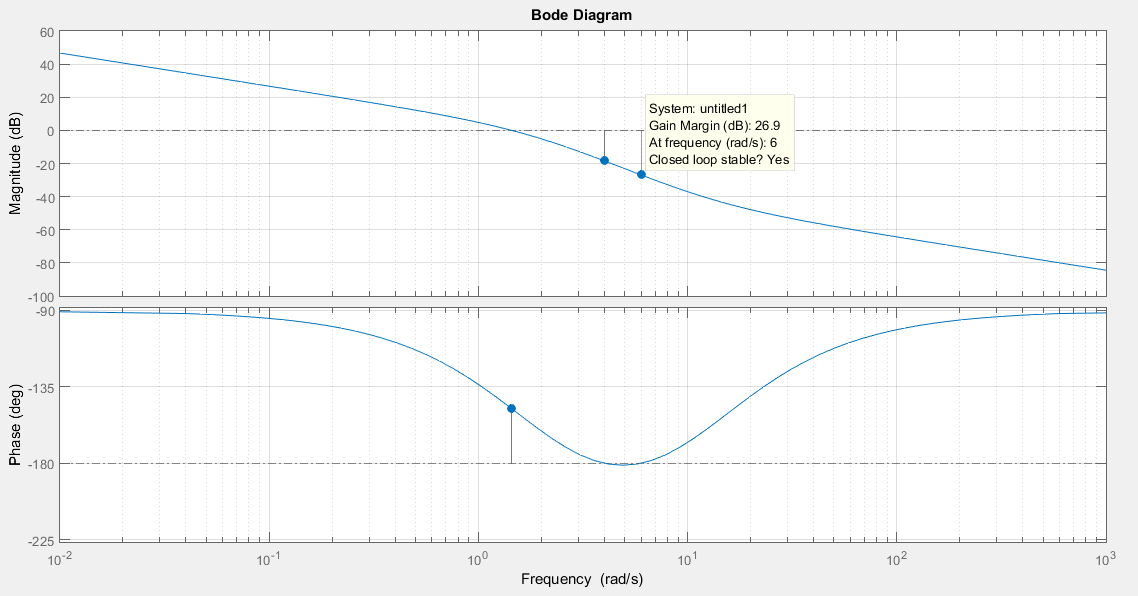
Gain margin
- The amount of additional gain that can be introduced into the system before it becomes unstable
- Determined by the distance between the 0 dB line and the magnitude plot at the frequency where the phase plot crosses -180 degrees in the Bode plot
- A positive gain margin indicates a stable system, while a negative gain margin indicates an unstable system
- A higher gain margin provides more robustness to variations in system gain
Phase margin
- The amount of additional phase lag that can be introduced into the system before it becomes unstable
- Determined by the distance between the -180 degree line and the phase plot at the frequency where the magnitude plot crosses the 0 dB line in the Bode plot
- A positive phase margin indicates a stable system, while a negative phase margin indicates an unstable system
- A higher phase margin provides more robustness to variations in system phase and time delays
- Adequate gain and phase margins are essential for ensuring the reliable operation of the closed-loop system in practical applications
Root locus and Bode plots
Root locus technique
- Graphical technique for analyzing the effect of varying the gain of a closed-loop system on its pole locations in the complex plane
- Shows the trajectories of the closed-loop poles as the system gain is varied from zero to infinity
- Determines the range of gains for which the closed-loop system remains stable
- Helps select an appropriate gain value for desired performance characteristics (damping ratio, settling time, overshoot)
- The root locus plot is symmetric about the real axis and starts at the open-loop poles and ends at the open-loop zeros
Bode plot and compensator design
- Used to analyze the frequency response of a closed-loop system and to design compensators for improving system performance
- Lag compensators improve the steady-state error and low-frequency performance by increasing the low-frequency gain
- Lead compensators improve the transient response and stability margins by increasing the phase margin at the desired crossover frequency
- Lag-lead compensators combine the benefits of both lag and lead compensation to achieve desired performance characteristics over a wide range of frequencies
- Compensators are designed by adjusting the pole and zero locations of the compensator transfer function
- The compensated system's Bode plot is obtained by adding the magnitude and phase plots of the original system and the compensator