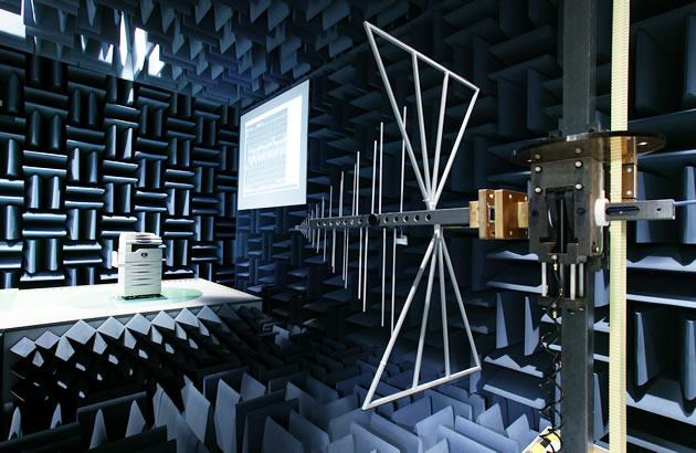
Anechoic chambers are essential for electromagnetic testing, providing controlled environments free from external interference. These specialized rooms use and to create isolated conditions for accurate measurements of emissions and susceptibility.

These chambers serve various purposes, from EMI/EMC testing to antenna characterization and acoustic evaluations. Their design incorporates wave absorption techniques, effective shielding, and optimized dimensions to meet specific testing requirements across different frequency ranges and applications.

Purpose of anechoic chambers

  • Provide controlled environments for electromagnetic testing crucial for EMI/EMC assessments
  • Eliminate external interference and reflections to ensure accurate measurements of electromagnetic emissions and susceptibility
  • Enable precise characterization of electromagnetic devices and systems in isolated conditions

EMI/EMC testing applications

Top images from around the web for EMI/EMC testing applications
  • Evaluate electronic devices for compliance with electromagnetic compatibility standards
  • Measure radiated emissions from equipment to identify potential sources of interference
  • Test susceptibility of devices to external electromagnetic fields
  • Simulate real-world electromagnetic environments for product development and troubleshooting

Antenna measurements

  • Characterize antenna radiation patterns in three-dimensional space
  • Determine antenna gain, directivity, and efficiency parameters
  • Measure antenna impedance and polarization characteristics
  • Validate antenna designs for various applications (wireless communications, radar systems)

Acoustic testing uses

  • Evaluate noise emissions from electronic and mechanical devices
  • Measure sound absorption and properties of materials
  • Test acoustic performance of audio equipment and speakers
  • Conduct psychoacoustic experiments in controlled sound environments

Design principles

  • Incorporate electromagnetic wave absorption techniques to minimize reflections
  • Implement effective shielding to isolate the chamber from external interference
  • Optimize chamber dimensions and layout for specific testing requirements

Electromagnetic wave absorption

  • Utilize materials with high magnetic and dielectric losses to attenuate incident waves
  • Implement pyramidal or wedge-shaped absorbers to create multiple reflections and increase path length
  • Design absorber structures to target specific frequency ranges of interest
  • Combine different absorber types to achieve broadband performance

Radio frequency shielding

  • Construct outer shell using conductive materials (copper, steel) to block external RF signals
  • Implement double-shielded designs for enhanced isolation in high-sensitivity applications
  • Incorporate RF-tight doors and access panels to maintain shielding integrity
  • Use specialized gaskets and seals to eliminate RF leakage at joints and seams

Size and shape considerations

  • Determine chamber dimensions based on lowest frequency of operation and required quiet zone size
  • Design tapered chamber shapes to reduce specular reflections
  • Account for equipment placement and movement within the chamber
  • Balance chamber size with practical constraints (cost, available space, structural limitations)

Chamber construction

  • Integrate multiple elements to create an effective anechoic environment
  • Combine absorber materials, shielding techniques, and structural design for optimal performance
  • Ensure proper installation and maintenance of all components for long-term reliability

Absorber materials

  • for high-frequency applications
  • for low-frequency absorption
  • combining multiple materials for broadband performance
  • Specialized absorbers for specific applications (EMC, radar cross-section measurements)

Ferrite tiles vs foam absorbers

  • Ferrite tiles offer superior low-frequency performance due to magnetic properties
  • Foam absorbers provide better high-frequency absorption and are lighter weight
  • Ferrite tiles have a flatter profile, suitable for space-constrained applications
  • Foam absorbers typically more cost-effective for large surface areas

Wall and floor treatments

  • Apply absorber materials in strategic patterns to maximize effectiveness
  • Install walkways and equipment supports compatible with absorber materials
  • Implement removable floor treatments for semi-anechoic configurations
  • Use specialized corner treatments to address reflection hotspots

Shielded enclosure requirements

  • Construct outer shell using welded metal panels for continuous shielding
  • Implement RF-tight doors with multiple contact points and pneumatic seals
  • Install filtered power and signal penetrations to maintain shielding integrity
  • Incorporate grounding systems to equalize potential and reduce unwanted currents

Types of anechoic chambers

  • Vary in design and capabilities to suit different testing requirements
  • Offer trade-offs between performance, cost, and versatility
  • Adapt to specific frequency ranges and measurement applications

Full anechoic chambers

  • Absorber treatment on all surfaces (walls, floor, ceiling) for complete isolation
  • Ideal for antenna pattern measurements and high-frequency EMC testing
  • Provide uniform in all directions
  • Typically more expensive and require larger spaces than

Semi-anechoic chambers

  • Absorber treatment on walls and ceiling, with reflective floor
  • Suitable for EMC and ground plane antenna measurements
  • Allow for easier equipment placement and cable routing
  • Can be converted to full anechoic by adding removable floor absorbers

Compact antenna test ranges

  • Utilize reflector systems to create plane wave conditions in a smaller space
  • Enable antenna measurements at shorter distances
  • Suitable for testing large antennas or low-frequency systems
  • Require precise alignment and surface accuracy of reflector systems

Key components

  • Integrate specialized equipment to facilitate accurate and efficient measurements
  • Ensure compatibility between measurement systems and chamber characteristics
  • Implement automation and control systems for repeatable testing procedures

Antenna positioners

  • Precision rotary joints for azimuth and elevation control
  • Linear slides for polarization and height adjustments
  • Computer-controlled positioning systems for automated measurements
  • Low-reflection materials and absorber coverings to minimize interference

Turntables and manipulators

  • Heavy-duty turntables for rotating large test objects
  • Multi-axis manipulators for complex positioning requirements
  • Load-bearing capabilities matched to test object weights
  • Integration with measurement software for synchronized data collection

Measurement equipment integration

  • Shielded equipment racks for analyzers and signal generators
  • Fiber optic links for high-speed data transmission without interference
  • Specialized cabling and connectors for minimal signal degradation
  • Remote control interfaces for equipment operation outside the chamber

Performance metrics

  • Quantify chamber effectiveness and suitability for specific applications
  • Provide benchmarks for comparing different chamber designs and configurations
  • Guide maintenance and upgrade decisions to maintain optimal performance

Reflectivity levels

  • Measure the amount of electromagnetic energy reflected by chamber surfaces
  • Typically expressed in decibels (dB) relative to incident wave strength
  • Vary with frequency and incident angle of electromagnetic waves
  • Lower indicate better chamber performance (-30 dB to -60 dB typical)

Quiet zone characteristics

  • Define the usable test volume within the chamber
  • Measure field uniformity and phase linearity within the quiet zone
  • Determine maximum test object size for accurate measurements
  • Vary with frequency and chamber design (typically 1/3 to 1/2 of chamber dimensions)

Frequency range capabilities

  • Specify the operational bandwidth of the anechoic chamber
  • Determined by absorber performance and chamber dimensions
  • Lower frequency limit often set by chamber size constraints
  • Upper frequency limit influenced by absorber design and surface accuracy

Testing procedures

  • Establish standardized methods for conducting measurements in anechoic chambers
  • Ensure repeatability and comparability of test results across different facilities
  • Adapt procedures to specific test requirements and equipment configurations

Equipment setup and calibration

  • Verify alignment and positioning of antennas and test objects
  • Perform system checks to ensure all components are functioning correctly
  • Calibrate measurement equipment using known reference standards
  • Conduct background noise measurements to establish baseline conditions

Measurement techniques

  • Implement far-field and measurement methods as appropriate
  • Utilize time-gating techniques to isolate desired signals from reflections
  • Apply pattern subtraction methods for improved accuracy in some applications
  • Employ statistical techniques for analyzing complex or time-varying signals

Data collection and analysis

  • Automate data acquisition to minimize human error and increase efficiency
  • Apply appropriate signal processing techniques (FFT, time-domain analysis)
  • Generate 2D and 3D visualizations of measurement results
  • Perform uncertainty analysis to quantify measurement accuracy and reliability

Limitations and challenges

  • Recognize inherent constraints of anechoic chamber technology
  • Address practical issues that impact chamber performance and usability
  • Develop strategies to mitigate limitations and optimize testing capabilities

Low frequency performance

  • Challenges in absorbing long wavelengths in limited space
  • Increased cost and size requirements for effective low-frequency chambers
  • Trade-offs between chamber size and low-frequency cut-off point
  • Hybrid solutions combining passive and active absorption techniques

Cost and maintenance issues

  • High initial investment for chamber construction and equipment
  • Ongoing maintenance requirements to preserve absorber and shielding integrity
  • Potential for damage to sensitive absorber materials during use
  • Calibration and verification costs to ensure continued performance

Space requirements

  • Large footprint needed for full-size chambers, especially at low frequencies
  • Structural considerations for supporting heavy shielding and equipment
  • HVAC and environmental control challenges in large enclosed spaces
  • Limitations on facility locations due to size and electromagnetic isolation needs

Alternatives to anechoic chambers

  • Provide options for EMI/EMC testing in different scenarios
  • Offer trade-offs between cost, accuracy, and test capabilities
  • Complement anechoic chamber measurements for comprehensive testing

Open area test sites

  • Outdoor facilities for EMC measurements in open environments
  • Require large, flat ground planes and minimal surrounding interference
  • Suitable for large equipment testing and some antenna measurements
  • Weather-dependent and potentially affected by ambient RF noise

Reverberation chambers

  • Highly reflective enclosures that create statistically uniform fields
  • Utilize mechanical stirrers to create time-varying electromagnetic environments
  • Efficient for radiated and total radiated power measurements
  • Limited in ability to measure directional characteristics of antennas or emissions

Simulation software options

  • Computational electromagnetic modeling tools (FDTD, MoM, FEM)
  • Enable virtual prototyping and preliminary design optimization
  • Reduce need for physical testing in early development stages
  • Limitations in modeling complex, real-world scenarios accurately

Future developments

  • Explore emerging technologies to enhance anechoic chamber performance
  • Address current limitations and expand testing capabilities
  • Adapt to evolving requirements in electromagnetic compatibility and antenna design

Advanced absorber materials

  • Metamaterial-based absorbers for improved low-frequency performance
  • Nano-engineered surfaces for broadband absorption characteristics
  • Active absorber systems that adapt to incident wave properties
  • Self-healing materials to increase durability and reduce maintenance

Hybrid chamber designs

  • Combination of anechoic and reverberation chamber principles
  • Reconfigurable chambers adaptable to different test requirements
  • Integration of active field cancellation techniques with passive absorption
  • Multi-purpose facilities for EMC, antenna, and acoustic testing

Miniaturization techniques

  • Compact designs for on-site testing and portable applications
  • Folded geometry chambers to reduce footprint while maintaining performance
  • Integration of anechoic principles into product enclosures for built-in testing
  • Scaled testing methods for high-frequency applications in smaller spaces

Key Terms to Review (31)

Absorber materials: Absorber materials are specialized substances used to reduce electromagnetic waves' reflection and transmission, thereby minimizing interference. They are crucial in designing anechoic chambers, where the goal is to create a controlled environment that allows for accurate testing and measurement of electromagnetic emissions. These materials help achieve an environment free from reflections, ensuring that the measurements taken are primarily due to the tested devices rather than external factors.
Absorbing materials: Absorbing materials are substances designed to reduce electromagnetic interference (EMI) by absorbing incident electromagnetic waves, thereby converting them into heat. These materials play a critical role in various applications where minimizing reflections and enhancing signal integrity is essential, such as in anechoic chambers, where the aim is to create an environment free from echoes and external noise.
Antenna Positioners: Antenna positioners are mechanical devices used to adjust the orientation and angle of antennas for optimal signal reception and transmission. These positioners can be controlled manually or automatically to ensure that antennas are aligned with specific signals or targets, which is crucial in various applications, including communication systems, radar systems, and anechoic chambers, where precise measurements are essential.
Antenna testing: Antenna testing is the process of evaluating an antenna's performance characteristics, including its efficiency, gain, radiation pattern, and impedance. This evaluation is crucial for ensuring that antennas function effectively in their intended applications, such as communication systems or broadcasting. Accurate antenna testing helps in optimizing designs, ensuring regulatory compliance, and improving overall system performance.
Attenuation: Attenuation refers to the reduction in strength or amplitude of a signal as it travels through a medium or system. This phenomenon is crucial in understanding how signals degrade over distance, which impacts wave propagation, transmission lines, and the effectiveness of various filtering and shielding methods.
Carbon-loaded foam absorbers: Carbon-loaded foam absorbers are materials designed to reduce electromagnetic interference (EMI) by absorbing electromagnetic waves. These absorbers consist of a foam matrix that is infused with carbon particles, which enhances their ability to attenuate unwanted signals across various frequencies, making them essential components in anechoic chambers where minimizing reflections is crucial for accurate measurements.
Compact antenna test ranges: Compact antenna test ranges (CATRs) are specialized facilities designed for measuring the performance of antennas in a controlled environment, minimizing reflections and other interferences. They utilize unique geometries and absorbing materials to create an effective testing space that simulates far-field conditions, allowing for accurate measurements of antenna characteristics in a compact area.
Compliance testing: Compliance testing is the process used to determine if a product or system meets specified requirements and standards for electromagnetic compatibility (EMC). This type of testing ensures that electronic devices operate as intended in their electromagnetic environment without causing unacceptable interference. Effective compliance testing typically involves controlled environments where measurements can be taken accurately, such as in anechoic chambers and open area test sites.
Conducted EMI: Conducted EMI refers to the unwanted electrical energy that travels along conductive paths, such as power lines or interconnecting cables, and can interfere with the performance of electronic devices. This type of interference can originate from various sources and propagate through these conductors, impacting the integrity of signals in sensitive electronics and leading to malfunctions.
EMI Receiver: An EMI receiver is a specialized instrument used to measure electromagnetic interference (EMI) signals in various environments, helping to identify sources of unwanted emissions and ensure compliance with electromagnetic compatibility standards. This tool is critical in evaluating radiated emissions from electronic devices, determining their impact on other equipment, and verifying that they meet regulatory requirements.
Emissions testing: Emissions testing is a procedure used to measure the electromagnetic emissions generated by electronic devices to ensure they comply with regulatory standards for electromagnetic compatibility. This testing is crucial for determining whether devices will cause interference with other electronic systems or be susceptible to such interference themselves. Proper emissions testing helps in the design and development of devices that operate safely within their intended environments without causing harmful disruptions.
Far-field: The far-field region refers to the area far enough away from a radiating source where the electromagnetic waves can be considered to be in a plane wave form, meaning the wavefronts are essentially flat. In this zone, the effects of distance on the electromagnetic fields become predictable and consistent, allowing for accurate measurements and analysis of radiated energy. This concept is crucial for applications such as testing antennas and assessing radiated emissions.
Ferrite Tiles: Ferrite tiles are electromagnetic absorbers made from ferrite materials that are used to reduce reflections and interference in anechoic chambers. These tiles play a crucial role in creating an environment free from external electromagnetic noise, allowing for accurate testing and measurement of electronic devices. Their composition and structure enable them to absorb electromagnetic waves across a range of frequencies, making them essential for effective EMC testing.
Frequency range capabilities: Frequency range capabilities refer to the ability of a device or system to operate effectively across a specific spectrum of frequencies. This aspect is crucial for ensuring that equipment can transmit and receive signals without interference or loss of performance, particularly in environments where various electromagnetic waves are present.
Full anechoic chambers: Full anechoic chambers are specialized environments designed to completely absorb sound and electromagnetic waves, creating an isolated space free from reflections and external interference. These chambers are essential for accurate testing and measurement in various fields, including telecommunications, electronics, and acoustics, as they eliminate unwanted noise and allow for precise evaluations of device performance.
Hybrid absorbers: Hybrid absorbers are specialized materials designed to effectively absorb electromagnetic waves, combining both resistive and reactive properties to enhance performance in various frequency ranges. These absorbers are crucial in anechoic chambers, as they minimize reflections and simulate free-space conditions, allowing for accurate testing and measurements of electronic devices without interference from stray signals.
Immunity Testing: Immunity testing is a process used to assess the ability of electronic devices to withstand electromagnetic interference (EMI) without malfunctioning. This type of testing is crucial for determining how well a device can operate in environments with various man-made EMI sources, ensuring reliability and performance in real-world applications.
ISO 3745: ISO 3745 is an international standard that specifies methods for determining the sound power level of noise sources using an anechoic chamber or a reverberation room. This standard is crucial for ensuring accurate measurements of sound levels, which is important in various fields, including product testing and compliance with regulations.
Measurement equipment integration: Measurement equipment integration refers to the process of combining various measurement devices and systems into a cohesive unit that can accurately assess electromagnetic emissions and susceptibility. This integration is crucial for ensuring that all components work together seamlessly to provide reliable data during testing in controlled environments, like anechoic chambers, where external interference is minimized.
MIL-STD-461: MIL-STD-461 is a military standard that establishes the requirements for the control of electromagnetic interference (EMI) for equipment and systems used by the Department of Defense (DoD). This standard ensures that military systems operate reliably in the presence of EMI, while also minimizing the electromagnetic emissions from these systems to prevent interference with other electronic devices.
Near-field: The near-field refers to the region close to a radiating source, where the electric and magnetic fields do not behave like plane waves and are more complex in nature. This area is critical for understanding how electromagnetic fields interact with nearby objects, making it essential in various applications such as anechoic chambers for accurate testing, radiated emissions testing to ensure compliance with regulations, and antenna design where characteristics like gain and directivity are influenced by proximity to the source.
Pre-compliance testing: Pre-compliance testing refers to a series of assessments conducted on electronic devices and systems to evaluate their compliance with electromagnetic compatibility (EMC) standards before formal certification. This process helps identify potential issues with radiated emissions and other compatibility problems early in the design phase, allowing engineers to make necessary adjustments and avoid costly redesigns or delays later on.
Quiet zone characteristics: Quiet zone characteristics refer to the specific environmental conditions that minimize electromagnetic interference, allowing for accurate testing and measurement in controlled settings. These characteristics are crucial for ensuring that anechoic chambers provide an environment free from unwanted reflections and noise, enabling precise evaluation of devices' performance in isolation from external influences.
Radiated EMI: Radiated EMI refers to electromagnetic interference that propagates through space via electromagnetic waves, affecting nearby electronic devices. This type of interference can arise from various sources, including electronic equipment, power lines, and wireless transmissions, impacting the performance and reliability of sensitive devices.
Radiated emissions testing: Radiated emissions testing is a procedure used to measure the electromagnetic energy emitted from electronic devices into the surrounding environment. This testing ensures that devices comply with regulatory limits for electromagnetic interference, which can disrupt the operation of other equipment and systems. It involves assessing the design and layout of circuits, considering how components interact with each other, and understanding the potential paths for emissions through apertures and seams in shielding.
Reflection: Reflection is the process by which electromagnetic waves bounce off a surface, changing direction while maintaining their energy. This phenomenon plays a critical role in understanding how waves interact with materials, affecting wave propagation, signal integrity, and the design of shielding mechanisms to mitigate interference.
Reflectivity Levels: Reflectivity levels refer to the measurement of how much electromagnetic energy is reflected off a surface compared to the amount that is incident on it. In the context of anechoic chambers, these levels are crucial for determining how well the chamber can absorb sound or electromagnetic waves, thereby ensuring that testing conditions are free from external interference.
Semi-anechoic chambers: Semi-anechoic chambers are specialized environments designed to minimize sound reflections and electromagnetic interference, primarily used for testing and measuring electronic devices. These chambers have absorptive materials on the walls, ceiling, and often the floor, which absorb sound and electromagnetic waves, allowing for accurate assessments of device performance in an isolated setting. The unique design typically features a conductive floor and may include a grounded metal mesh ceiling to facilitate various types of testing, including emissions and immunity assessments.
Shielding: Shielding is the process of protecting electronic components from electromagnetic interference (EMI) by enclosing them in a conductive or magnetic material. This method helps to reduce unwanted noise and maintain signal integrity by blocking or redirecting electromagnetic fields that can disrupt the normal functioning of electronic devices.
Signal generator: A signal generator is a device that produces electrical signals with specific characteristics, such as frequency and amplitude, used in testing and designing electronic equipment. These signals can simulate various real-world conditions that devices may encounter, making them crucial for evaluating performance in different environments. Signal generators are integral to compliance testing, ensuring that electronic products meet regulatory standards, and are also utilized in anechoic chambers and immunity testing to assess how devices respond to interference.
Turntables and Manipulators: Turntables and manipulators are devices used in testing and measuring electromagnetic compatibility and interference in anechoic chambers. They allow for precise positioning and orientation of test samples or antennas, ensuring accurate measurement of radiation patterns and interference effects. These devices play a crucial role in simulating real-world conditions while minimizing reflections and external noise, enhancing the reliability of test results.
© 2024 Fiveable Inc. All rights reserved.
AP® and SAT® are trademarks registered by the College Board, which is not affiliated with, and does not endorse this website.