Single point grounding is a crucial technique in EMC design that minimizes ground loops and reduces electromagnetic interference. By establishing a single reference point for all ground connections, it creates a controlled path for return currents, maintaining signal integrity and reducing noise in sensitive electronic systems.
This method connects all ground points to a common reference, eliminating multiple ground paths and providing a low-impedance return for currents. It enhances system stability, reduces emissions, and simplifies troubleshooting. However, practical implementation faces challenges due to non-zero conductor impedance and physical layout constraints.
Concept of single point grounding
- Fundamental grounding technique in electromagnetic compatibility (EMC) design aims to minimize ground loops and reduce electromagnetic interference
- Establishes a single reference point for all ground connections within a system, creating a controlled path for return currents
- Crucial for maintaining signal integrity and reducing noise in sensitive electronic systems
Definition and purpose
- Grounding method connects all ground points to a single, common reference point
- Eliminates multiple ground paths, reducing the potential for ground loops and associated noise
- Provides a low-impedance return path for currents, minimizing voltage differences between different parts of the system
- Enhances overall system stability and reduces electromagnetic emissions
Advantages over multi-point grounding
- Reduces ground loop area, minimizing induced voltages from external electromagnetic fields
- Simplifies troubleshooting by providing a clear, identifiable ground reference point
- Improves common-mode rejection in differential signaling systems
- Decreases the likelihood of creating unintended antennas formed by ground loops
Ideal vs practical implementation
- Ideal implementation assumes zero impedance in grounding conductors and perfect equipotential surface
- Practical systems face challenges due to non-zero conductor impedance and physical layout constraints
- Requires careful design considerations to approach ideal performance in real-world applications
- May involve compromises between theoretical optimum and practical limitations (cable lengths, component placement)
Components of single point system
- Essential elements work together to create an effective single point grounding system
- Proper selection and implementation of these components significantly impact EMC performance
- Design must consider the interaction between components to achieve optimal grounding effectiveness
Ground bus bar
- Serves as the central connection point for all ground connections in the system
- Typically made of highly conductive material (copper) to minimize resistance
- Dimensions chosen based on current-carrying capacity and number of connections required
- May include multiple mounting points for secure attachment to the chassis or enclosure
Star configuration
- Radial arrangement of ground connections emanating from the central ground point
- Minimizes interactions between different ground currents by providing separate paths
- Reduces common impedance coupling between circuits
- Requires careful planning of physical layout to maintain optimal star topology
Grounding conductors
- Connect individual circuit elements or subsystems to the central ground point
- Selection based on current-carrying capacity, frequency of operation, and length
- May use different types of conductors (stranded wire, flat braids, solid bars) depending on application
- Proper sizing and routing critical for maintaining low impedance across the frequency range of interest
Design considerations
- Crucial factors in achieving effective single point grounding in EMC systems
- Require a holistic approach, considering electrical, mechanical, and electromagnetic aspects
- Impact system performance, reliability, and compliance with EMC standards
- Often involve trade-offs between ideal performance and practical implementation constraints
Impedance minimization
- Focuses on reducing the overall impedance of the grounding system
- Utilizes short, thick conductors to minimize resistance and inductance
- Considers skin effect at high frequencies, employing flat braids or copper straps
- Implements proper bonding techniques to reduce contact resistance at connection points
Current path analysis
- Examines the flow of return currents through the grounding system
- Identifies potential areas of current concentration or unintended paths
- Uses techniques like partial inductance analysis to optimize conductor placement
- Considers both low-frequency conduction currents and high-frequency displacement currents
Frequency dependence
- Recognizes that grounding system behavior changes with frequency
- Addresses skin effect and increased inductance at higher frequencies
- Implements frequency-dependent grounding strategies (separate high and low-frequency grounds)
- Utilizes distributed capacitance and inductance to maintain performance across a wide frequency range
Applications in EMC
- Single point grounding plays a crucial role in various EMC mitigation strategies
- Enhances overall system immunity to electromagnetic interference
- Reduces emissions from electronic systems, aiding in regulatory compliance
- Improves signal integrity in sensitive analog and digital circuits
Noise reduction techniques
- Implements ground planes to provide low-impedance return paths for high-frequency currents
- Utilizes proper shielding techniques in conjunction with single point grounding
- Employs ground isolation methods to separate noisy and sensitive circuits
- Implements controlled impedance transmission lines with well-defined ground references
Common mode rejection
- Enhances the effectiveness of differential signaling by providing a stable ground reference
- Reduces common-mode noise through symmetrical grounding of differential pairs
- Implements common-mode chokes in conjunction with single point grounding for improved performance
- Utilizes balanced circuit topologies to maximize common-mode rejection ratio (CMRR)
Ground loop prevention
- Eliminates multiple ground paths that can form large loop antennas
- Reduces induced voltages from external magnetic fields by minimizing loop areas
- Implements isolation techniques (optical, transformer) to break potential ground loops
- Utilizes single point ground connections for cable shields to prevent shield current loops
Implementation challenges
- Practical limitations often hinder the ideal implementation of single point grounding
- Requires careful consideration of system layout, component placement, and interconnections
- May necessitate compromises between optimal grounding and other design constraints
- Demands ongoing assessment and refinement throughout the design and testing process
Physical constraints
- Limited space in compact designs may restrict ideal grounding conductor routing
- Component placement dictated by other factors (thermal, mechanical) may compromise grounding layout
- Challenges in maintaining star configuration in complex, multi-board systems
- Difficulties in accessing a single ground point in large or distributed systems
High frequency limitations
- Increased impedance of grounding conductors at high frequencies due to skin effect and inductance
- Resonances in grounding structures can create unintended antennas at specific frequencies
- Parasitic capacitances between grounding conductors and other system elements
- Challenges in maintaining equipotential surfaces at wavelengths shorter than physical dimensions
Bonding methods
- Ensuring low-impedance connections between grounding conductors and reference planes
- Selecting appropriate bonding techniques for different materials (soldering, welding, compression)
- Addressing corrosion and long-term reliability of grounding connections
- Implementing proper surface preparation and cleaning procedures for effective bonding
Single point vs distributed grounding
- Compares two fundamental grounding philosophies in EMC design
- Evaluates the strengths and weaknesses of each approach in different applications
- Considers the impact on system performance, cost, and complexity
- Explores situations where a combination of both techniques may be beneficial
Performance comparison
- Single point grounding excels in low-frequency applications and smaller systems
- Distributed grounding often performs better in high-frequency and large-scale systems
- Single point systems typically offer better control of low-frequency ground currents
- Distributed systems can provide lower impedance paths for high-frequency return currents
Suitability for different systems
- Single point grounding well-suited for audio systems and low-frequency analog circuits
- Distributed grounding often preferred in high-speed digital systems and RF applications
- Single point approach beneficial in systems with clearly defined signal flow and limited bandwidth
- Distributed grounding advantageous in complex systems with multiple interconnected subsystems
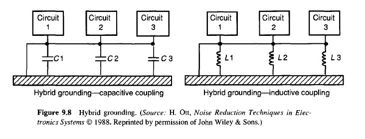
Hybrid approaches
- Combines elements of both single point and distributed grounding techniques
- Implements segmented ground planes with controlled interconnections
- Utilizes frequency-dependent grounding strategies (single point for low frequencies, distributed for high frequencies)
- Employs local single point grounds within a larger distributed grounding framework
Testing and verification
- Critical phase in ensuring the effectiveness of single point grounding implementation
- Involves a combination of measurement techniques and analytical methods
- Helps identify potential issues and validate the grounding system's performance
- Provides data for optimization and compliance documentation
Impedance measurements
- Utilizes network analyzers or impedance analyzers to characterize grounding system
- Measures DC resistance and AC impedance across the frequency range of interest
- Identifies resonances and unexpected behavior in the grounding structure
- Compares measured values against design targets and theoretical predictions
Current distribution analysis
- Employs current probes to measure the flow of currents in various parts of the grounding system
- Identifies unintended current paths and potential ground loops
- Utilizes thermal imaging to detect areas of high current concentration
- Compares measured current distribution with expected behavior from simulations
EMI reduction assessment
- Conducts near-field and far-field electromagnetic emissions measurements
- Compares emissions levels before and after implementation of single point grounding
- Evaluates the effectiveness of grounding in reducing common-mode emissions
- Assesses impact on system immunity through conducted and radiated susceptibility tests
Regulatory compliance
- Ensures that single point grounding implementations meet industry standards and regulations
- Addresses safety concerns related to grounding in electrical systems
- Provides guidelines for documentation and certification processes
- Considers specific requirements for different industries and applications
Standards for single point grounding
- Incorporates guidelines from IEC 61000 series for electromagnetic compatibility
- Addresses grounding requirements in safety standards (IEC 60950 for IT equipment)
- Considers military standards (MIL-STD-461) for EMC in defense applications
- Implements recommendations from industry-specific standards (DO-160 for aerospace)
Industry-specific requirements
- Automotive industry (ISO 11452) focuses on vehicle-level EMC and grounding
- Medical device standards (IEC 60601) emphasize patient safety and equipment grounding
- Telecommunications equipment (ETSI EN 300 386) addresses grounding for network infrastructure
- Industrial automation (IEC 61800) considers grounding in variable frequency drive systems
Documentation and certification
- Develops comprehensive grounding diagrams and schematics
- Prepares test reports demonstrating compliance with relevant standards
- Implements configuration management for grounding system design and modifications
- Obtains third-party certification when required by regulatory bodies or customers
Troubleshooting common issues
- Addresses frequently encountered problems in single point grounding systems
- Provides strategies for identifying and resolving grounding-related issues
- Considers both electrical and mechanical aspects of grounding system failures
- Emphasizes the importance of systematic troubleshooting approaches
Ground potential differences
- Measures voltage differences between various points in the grounding system
- Identifies sources of ground currents causing potential differences
- Implements additional bonding or rerouting of ground connections to minimize differences
- Considers the use of equipotential bonding conductors in large systems
Parasitic capacitance effects
- Recognizes unintended capacitive coupling between grounding conductors and other system elements
- Utilizes shielding techniques to minimize capacitive coupling
- Implements proper routing and spacing of grounding conductors to reduce parasitic capacitance
- Considers the use of guard traces or planes in sensitive analog circuits
Resonance problems
- Identifies resonant frequencies in grounding structures through impedance measurements
- Modifies grounding conductor lengths or geometries to shift resonances out of the band of interest
- Implements damping techniques to reduce the impact of unavoidable resonances
- Considers the use of ferrite beads or other lossy elements to control high-frequency resonances
Future trends and advancements
- Explores emerging technologies and methodologies in grounding system design
- Addresses challenges posed by increasing operating frequencies and system complexities
- Considers the impact of new materials and manufacturing techniques on grounding implementations
- Examines the integration of grounding strategies with other aspects of EMC design
High-speed circuit adaptations
- Develops grounding techniques for circuits operating in the millimeter-wave frequency range
- Explores the use of artificial ground planes and metamaterials for improved high-frequency performance
- Implements active grounding systems to dynamically adjust to changing operating conditions
- Utilizes advanced simulation tools for accurate prediction of grounding behavior at very high frequencies
Integration with wireless systems
- Addresses grounding challenges in systems combining wired and wireless interfaces
- Develops strategies for maintaining signal integrity in mixed-signal wireless devices
- Explores the impact of intentional radiators on grounding system performance
- Implements adaptive grounding techniques to optimize performance across different operating modes
Emerging grounding technologies
- Investigates the use of graphene and other 2D materials in grounding applications
- Explores the potential of superconducting elements in low-temperature electronics grounding
- Develops grounding strategies for flexible and wearable electronic systems
- Implements machine learning algorithms for real-time optimization of grounding systems in complex environments