OSI Reference Model
The OSI Reference Model divides network communication into seven distinct layers, from physical signals on a wire up to user-facing applications. It gives network engineers and students a shared vocabulary for describing where a particular function lives in the networking stack, and it's the standard framework for reasoning about how protocols interact, how data flows, and where problems occur during troubleshooting.
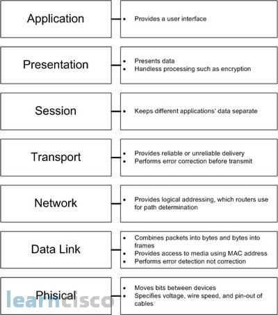
Seven Layers of the OSI Model
Each layer has a well-defined role and provides services to the layer above it while consuming services from the layer below. Here's what each one does, starting from the top.
Application Layer (Layer 7) is the layer closest to the end user. It doesn't refer to applications themselves (like your web browser), but rather to the protocols those applications rely on: HTTP for web traffic, SMTP for email, DNS for name resolution, FTP for file transfers. This layer defines how applications on different hosts initiate and structure their communication.
Presentation Layer (Layer 6) handles data translation between the format an application uses and the format the network expects. Three core jobs live here: data format conversion (e.g., translating between ASCII and Unicode), encryption/decryption (e.g., TLS operations), and data compression. Think of it as the layer that makes sure both sides agree on how the data is represented.
Session Layer (Layer 5) manages the dialogs between two communicating applications. It establishes, maintains, and tears down sessions. It also introduces synchronization points (checkpoints), so if a long transfer is interrupted, the session can resume from the last checkpoint rather than starting over.
Transport Layer (Layer 4) is responsible for end-to-end delivery between processes on different hosts. It segments large messages into smaller units and reassembles them at the destination. Two key service models exist here:
- Connection-oriented (TCP): reliable delivery with error checking, flow control, and congestion control
- Connectionless (UDP): lightweight, best-effort delivery with minimal overhead
Network Layer (Layer 3) deals with logical addressing and routing. Every device gets a logical address (an IP address), and this layer determines the best path for packets to travel across interconnected networks. Routing protocols like OSPF (for intra-domain) and BGP (for inter-domain) operate here. This is the layer that makes communication between different networks possible.
Data Link Layer (Layer 2) takes packets from the Network Layer and organizes them into frames for transmission over a specific physical link. It uses MAC addresses to identify devices on the same local network. Error detection happens here through mechanisms like CRC (Cyclic Redundancy Check). Protocols at this layer include Ethernet (for LANs) and PPP (for point-to-point links). Note that the Data Link Layer detects errors but typically does not correct them; it usually just discards corrupted frames.
Physical Layer (Layer 1) defines the hardware-level details: cable types, connector pin layouts, wireless frequencies, voltage levels, signal timing, and modulation schemes. Its job is converting a stream of bits into physical signals (electrical, optical, or radio) and vice versa.
Services Between Layers
Each layer provides a specific service abstraction to the layer above it, hiding the complexity below:
- Physical → Data Link: raw bit transmission over the medium
- Data Link → Network: error-detected frame delivery across a single link
- Network → Transport: logical addressing and routing across multiple networks
- Transport → Session: reliable (or unreliable) end-to-end data delivery between processes
- Session → Presentation: managed dialog sessions with synchronization
- Presentation → Application: data format translation, encryption, and compression
- Application → End User: protocol-level services that applications consume directly
The key idea is that each layer only needs to understand the interface to its immediate neighbors. A transport protocol doesn't care whether the physical medium is fiber optic or copper; that detail is abstracted away by the layers below.

Data Encapsulation in the OSI Model
As data moves down the stack on the sending side, each layer wraps it with its own header (and sometimes a trailer). This process is called encapsulation, and each layer's unit of data gets a specific name.
Encapsulation (sender side):
- Application Layer generates the user data
- Presentation Layer formats, compresses, or encrypts it
- Session Layer adds session control information
- Transport Layer segments the data and adds a transport header → produces a segment
- Network Layer adds a network header (source/destination IP) → produces a packet
- Data Link Layer adds a frame header and trailer (including MAC addresses and CRC) → produces a frame
- Physical Layer converts the frame into a stream of bits for transmission
Decapsulation (receiver side) reverses this process exactly:
- Physical Layer receives bits, reconstructs the frame
- Data Link Layer strips the frame header/trailer, checks for errors, passes the packet up
- Network Layer strips the packet header, passes the segment up
- Transport Layer strips the transport header, reassembles the data, passes it up
- Session Layer strips session information
- Presentation Layer decrypts/decompresses and converts the data format
- Application Layer receives the original user data
The important thing to remember: at each layer, the entire unit from the layer above is treated as opaque payload. The Network Layer doesn't inspect what's inside the segment; it just wraps it with its own header and passes it down.
OSI Model vs. TCP/IP Suite
The OSI model is a conceptual reference framework developed by ISO. The TCP/IP model is the actually implemented protocol suite that runs the internet. They share the idea of layered architecture, but differ in structure and philosophy.
| OSI Model | TCP/IP Model | Notes |
|---|---|---|
| Application (Layer 7) | Application | TCP/IP merges the top three OSI layers |
| Presentation (Layer 6) | Application | into a single Application layer. Functions |
| Session (Layer 5) | Application | like encryption and sessions are handled by individual protocols (e.g., TLS, RPC). |
| Transport (Layer 4) | Transport | Direct correspondence. TCP and UDP live here in both models. |
| Network (Layer 3) | Internet | Direct correspondence. IP operates here. |
| Data Link (Layer 2) | Network Access | TCP/IP merges the bottom two OSI layers |
| Physical (Layer 1) | Network Access | into a single Network Access (or Link) layer. |
A few distinctions worth noting:
- The OSI model was designed before its protocols were built, as a top-down theoretical framework. TCP/IP grew around protocols that already existed and worked.
- In practice, the Presentation and Session layers from OSI don't map cleanly to separate, distinct protocols in real networks. Their functions (encryption, session management) are typically folded into application-layer or transport-layer protocols.
- The OSI model remains valuable as a teaching and reference tool, even though TCP/IP is what you'll encounter in actual network implementations.